


1-12
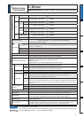
Function
Control input
(1) Servo-ON input (2) Alarm clear input (3) Gain switching input
(4)
Positive direction over-travel inhibition input
(5)
Negative direction over-travel inhibition input
(6) Forced alarm input
(7) Inertia ratio switching input
Control output
(1) Servo-Alarm output (2) Servo-Ready output (3) External brake release signal
6SHHGDUULYDORXWSXW7RUTXHLQOLPLWVLJQDORXWSXW
(6) Zero-speed detection output signal (7) Alarm output (8) Alarm attribute output
Position control
Control input
(1) Deviation counter clear (2) Command pulse inhibition
(3) Command dividing gradual increase switching (4) Damping control switching
7RUTXHOLPLWVZLWFKLQJ&RQWUROPRGHVZLWFKLQJ
Control output (1) Positioning complete (In-position) (2)Positional command ON/OFF output
Pulse
input
Max. command
SXOVHIUHTXHQF\
Exclusive interface for Photo-coupler: 500kpps
Exclusive interface for line driver : 4Mpps
Input pulse signal
format
Differential input. Selectable with parameter. ((1) Positive and Negative direction,
(2) A and B-phase, (3) Command and direction)
Electronic gear
(Division/Multiplication of
command pulse)
3URFHVVFRPPDQGSXOVHIUHTXHQF\ðHOHFWURQLFJHDUUDWLR
(
1 to 2
30
1 to 2
30
)
as positional command
input. Use electronic gear ratio in the range 1/1000 to 1000 times.
6PRRWKLQJÀOWHU 3ULPDU\GHOD\ÀOWHURU),5W\SHÀOWHULVDGDSWDEOHWRWKHFRPPDQGLQSXW
Analog
input
7RUTXHOLPLW
command input
,QGLYLGXDOWRUTXHOLPLWIRUERWKSRVLWLYHDQGQHJDWLYHGLUHFWLRQLVHQDEOHG
7RUTXHIHHGIRUZDUGLQSXW
$QDORJYROWDJHFDQEHXVHGDVWRUTXHIHHGIRUZDUGLQSXW
Instantaneous Speed Observer
Available
Damping Control Available
Velocity control
Control input
(1) Selection of internal velocity setup (2) Speed zero clamp
(3) Speed command sign input (4)Control mode switching
Control output (1) Speed coincidence output (2)Speed command ON/OFF output
Analog
input
Velocity command
input
Speed command input can be provided by means of analog voltage.
Parameters are used for scale setting and command polarity.
(6V/Rated rotational speed Default)
7RUTXHOLPLW
command input
,QGLYLGXDOWRUTXHOLPLWIRUERWKSRVLWLYHDQGQHJDWLYHGLUHFWLRQLVHQDEOHG
7RUTXHIHHGIRUZDUGLQSXW
$QDORJYROWDJHFDQEHXVHGDVWRUTXHIHHGIRUZDUGLQSXW
Internal velocity command Switching the internal 8speed is enabled by command input.
Soft-start/down function
Individual setup of acceleration and deceleration is enabled, with 0 to 10s/1000r/min.
Sigmoid acceleration/deceleration is also enabled.
Zero-speed clamp 0-clamp of internal velocity command with speed zero clamp input is enabled.
Instantaneous Speed Observer
Available
7RUTXHFRQWURO
Control input 6SHHG]HURFODPS7RUTXHFRPPDQGVLJQLQSXW&RQWUROPRGHVZLWFKLQJ
Control output (1) Speed coincidence output (2) Speed in-limit output
Analog
input
7RUTXHFRPPDQG
input
7RUTXHFRPPDQGLQSXWFDQEHSURYLGHGE\PHDQVRIDQDORJYROWDJH
3DUDPHWHUVDUHXVHGIRUVFDOHVHWWLQJDQGFRPPDQGSRODULW\9UDWHGWRUTXH'HIDXOW
Speed limit function Speed limit value with parameter t is enabled.
Full-closed control
Control input
(1) Deviation counter clear (2) Command pulse inhibition
(3) Command dividing gradual increase switching (4) Damping control switching
7RUTXHOLPLWVZLWFKLQJ
Control output (1) Full-closed positioning complete (2) Positional command ON/OFF output
Pulse
input
Max. command
SXOVHIUHTXHQF\
Exclusive interface for Photo-coupler: 500kpps
Exclusive interface for line driver : 4Mpps
Input pulse signal
format
Differential input. Selectable with parameter. ((1) Positive and Negative direction, (2) A and
B-phase, (3) Command and direction)
Electronic gear
(Division/Multiplication of
command pulse)
3URFHVVFRPPDQGSXOVHIUHTXHQF\ðHOHFWURQLFJHDUUDWLR
(
1 to 2
30
1 to 2
30
)
as positional command
input. Use electronic gear ratio in the range 1/1000 to 1000 times.
6PRRWKLQJÀOWHU 3ULPDU\GHOD\ÀOWHURU),5W\SHÀOWHULVDGDSWDEOHWRWKHFRPPDQGLQSXW
Analog
input
7RUTXHOLPLW
command input
,QGLYLGXDOWRUTXHOLPLWIRUERWKSRVLWLYHDQGQHJDWLYHGLUHFWLRQLVHQDEOHG
7RUTXHIHHGIRUZDUGLQSXW
$QDORJYROWDJHFDQEHXVHGDVWRUTXHIHHGIRUZDUGLQSXW
Setup range of division/
multiplication of feedback
scale
1/40 to 160 times
The ratio of encoder pulse (numerator) to external scale pulse (denominator) can be set to 1 to 2
20
(numerator) to 1 to 2
20
(denominator), but should be set to a ratio within the range shown above.
Common
Auto tuning
The load inertia is identified in real time by the driving state of the motor operating according
WRWKHFRPPDQGJLYHQE\WKHFRQWUROOLQJGHYLFHDQGVHWXSVXSSRUWVRIWZDUH´3$1$7(50µ
The gain is set automatically in accordance with the rigidity setting.
Division of encoder feedback pulse
Set up of any value is enabled (encoder feedback pulses count is the max.).
Protective
function
Hard error
Over-voltage, under-voltage, over-speed, over-load,
over-heat, over-current and encoder error etc.
Soft error Excess position deviation, command pulse division error, EEPROM error etc.
Traceability of alarm data The alarm data history can be referred to.
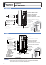
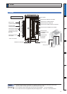
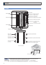
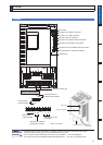
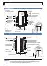
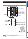
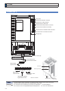
2. Driver
Specifications (Velocity, position, torque, full-closed control type)