


7-5
1
Before Using the Products
2
Preparation
3
Connection
4
Setup
5
Adjustment
6
When in Trouble
7
Supplement
7
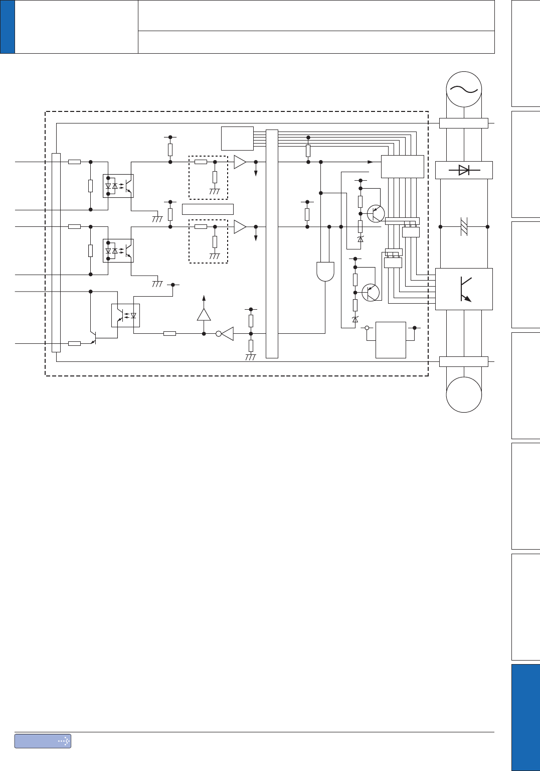
1. Safety function
Supplement
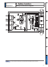
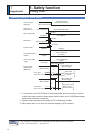
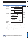
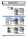
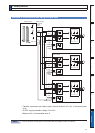
Safety Circuit Block Diagram
Power
LPF 3ms
Control
Circuit
Motor
M
ASIC
PC
PC
I_SF1
IL_EMG
I_SF2
O_EDM
('0ï
EDM+
6)ï
SF2+
SF1+
6)ï
X3
Power section interface
4
3
6
5
8
7
+5V
+5V
+5V
+5V
+5V
+5V
in
+5V
out
+5V
+5V
5V
5V
3.3V
level
shifter
N
μC
analog
input
μC
analog
input
μC port
+5V PS
Voltage
Monitor
IL_ERR1
Note
2QO\IRUSRVLWLRQFRQWUROW\SHLVQRWSURYLGHGZLWK;6DIHW\IXQFWLRQFRQQHFWRU