


7-11
1
Before Using the Products
2
Preparation
3
Connection
4
Setup
5
Adjustment
6
When in Trouble
7
Supplement
7
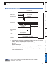
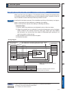
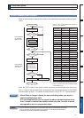
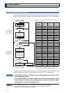
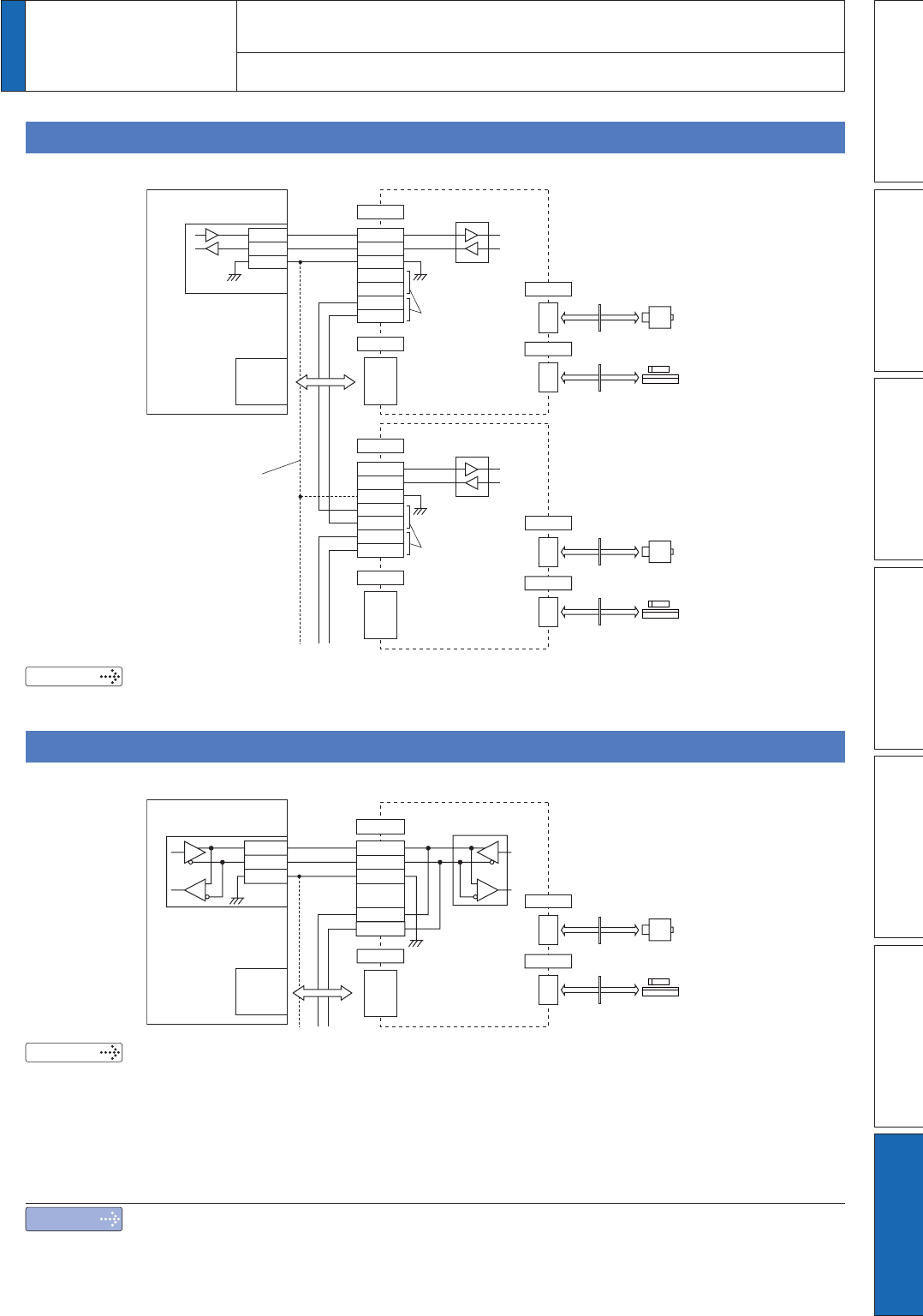
2. Absolute system
Supplement
Configuration
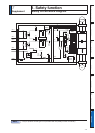
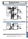
* No connection to X5 when no
external scale is used.
Host controller
RS232
interface
SN751701
or equivalent
Motor
Relay
connector
Positioning
controller
TXD
RXD
GND
4
3
1
Servo driver
RXD
TXD
GND
6
RS485+
5
8
7
RS485ï
RS485+
RS485ï
X2
RS485 can be
connecter to either
terminal pair.
X4
X6
Detection
head
External scale unit
Relay
connector
X5
SN751701
or equivalent
Motor
Relay
connector
4
3
1
RXD
TXD
GND
6
RS485+
5
RS485ï
8
RS485+
7
RS485ï
X2
X4
X6
Detection
head
External scale unit
Relay
connector
X5
RS485 can be
connecter to either
terminal pair.
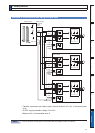
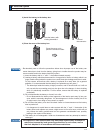
When longer wirings
are used and/or drivers
are connected to
different power
sources, interconnect
GND terminals of these
drivers to prevent
potential generation.
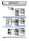
&RQÀJXUDWLRQRIDEVROXWHV\VWHPRIVFDOHXVLQJ56LQWHUIDFH
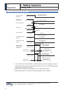
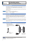
&RQÀJXUDWLRQRIDEVROXWHV\VWHPRIVFDOHXVLQJ56LQWHUIDFH
Related page
3´&RQQHFWLRQRI&RPPXQLFDWLRQ/LQHµ
Related page
3´&RQQHFWLRQRI&RPPXQLFDWLRQ/LQHµ
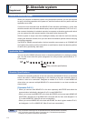
* No connection to X5 when no
external scale is used.
Motor
Relay
connector
X4
X6
Detection
head
External scale unit
Relay
connector
X5
RS485
interface
ADM485
or equivalent
RS485+
RS485–
GND
8
7
Servo driver
X2
RS485+
6
5
1
RS485–
GND
RS485+
RS485–
Host controller
Positioning
controller
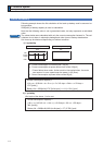
Note
*
Battery for absolute encoder is required to store the multi-turn data into the encoder.
Connect the battery between BAT+ and BAT– of the motor.
2QO\IRUSRVLWLRQFRQWUROW\SHLVQRWSURYLGHGZLWK;&RPPXQLFDWLRQFRQQHFWRU
2QO\IRUSRVLWLRQFRQWUROW\SHGRHVQRWVXSSRUWWKHELWDEVROXWHVSHFLÀFDWLRQ
,WVXSSRUWVRQO\ELWLQFUHPHQWDOVSHFLÀFDWLRQ