


2-21
1
Before Using the Products
2
Preparation
3
Connection
4
Setup
5
Adjustment
6
When in Trouble
7
Supplement
P.2-22
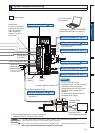
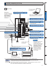
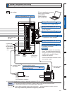
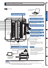
Short circuit wire
(B2-B3)
Ground
(earth)
Ground
terminal
Charge lamp
(Red LED)
*1
Junction cable
for brake
DC Power supply for brake
DC24V
(to be supplied by customer)
Junction cable for motor
Junction cable
for encoder
: High voltage
U-phase(red)
V-phase(white)
W-phase(black)
*1 Do not make displacement, wiring or inspection while the LED is lit - cause of electric shock.
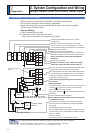
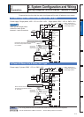
0RQLWRURXWSXW
:LULQJWR&RQQHFWRU; P.2-60
PC (to be supplied by customer)
Setup support software
´3$1$7(50µ
Please download
from our web site.
&RQQHFWLRQWR3&3$1$7(50
&RQQHFWLRQWR5656
or host controller
&RQQHFWLRQWR6DIHW\E\SDVVSOXJ
&RQQHFWLRQWRencoder
&RQQHFWLRQWRfeedback scale
&RQQHFWLRQWRKRVWFRQWUROOHU
:LULQJWR&RQQHFWRU; P.2-57
:LULQJWR&RQQHFWRU; P.2-55
:LULQJWR&RQQHFWRU; P.2-54
:LULQJWR&RQQHFWRU; P.2-53
:LULQJWR&RQQHFWRU; P.2-51
:LULQJWR&RQQHFWRU; P.2-51
&RQQHFWLRQWRPRWRUGULYLQJ
SKDVHDQGJURXQG
* These colors are
used for optional
cable.
;WR;DUHXVHGIRUWKHVHFRQGDU\
circuit. To connect these terminals to
the primary power supply (particularly,
24 VDC power supply for brake),
insulation is required.
Do not connect these terminals to the
same power supply.
5HPDUNV
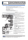
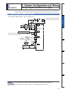
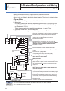
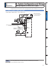
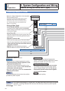
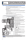
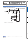
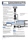
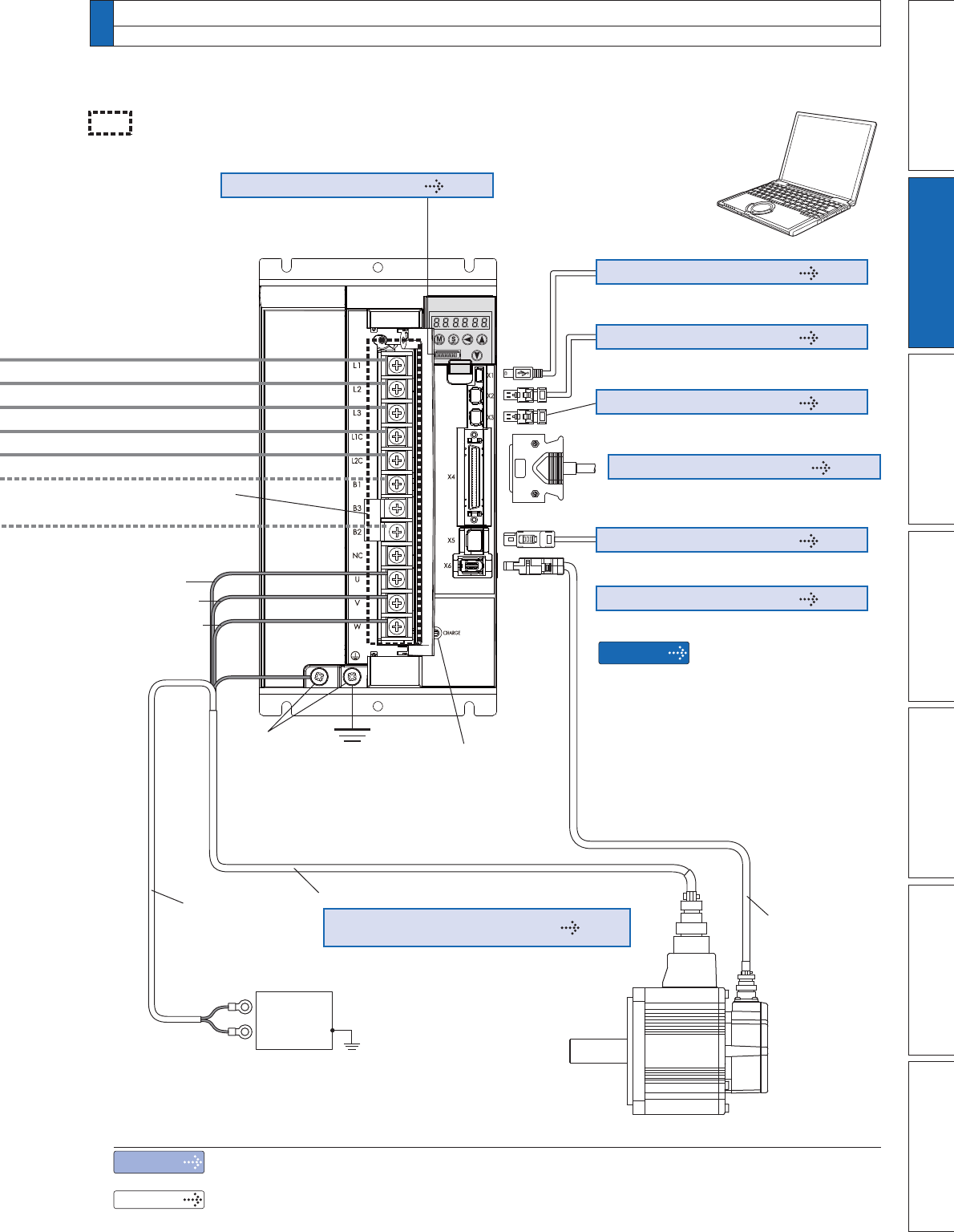
2. 6\VWHP&RQÀJXUDWLRQDQG:LULQJ
Overall Wiring (F-frame, 200 V type)
Note
Related page
7KHÀJXUHDERYHVKRZVFRQQHFWLRQVRQYHORFLW\SRVLWLRQWRUTXHDQGIXOOFORVHGPRGHGULYHU
Only for position control type is not provided with X2, X3 and X5.
3´
Wiring of the Main Circuit
)IUDPH9W\SHµ3´6SHFLÀFDWLRQVRI0RWRUFRQQHFWRUµ
URL: http://industrial.panasonic.com/jp/i/fa_motor.html