


1-16
E-frame (200 V)
B1
B3
N
P
Error
detection
Voltage
detection
Sequence control
B2
L1C
L2C
Division
processing
DC/DC
X6
U
V
W
M
RE
+
(12V
+5V
PS for gate drive
PS for RE
Fuse
Parameter control
EEPROM
Fan
Front panel
Display
operation
control
Protective
curcuit
Alarm
signal
Pulse train
command
Pusle
output
Analog
velocity
command
Control
input
Control
output
Division/
mulitiplication
+
+
–
–
A/D
A/D
16-bit
Position
Speed
Velocity
Tor que
Internal
External
Deviation
counter
Internal speed
command
Speed
detection
Position
deviation amp.
Speed
deviation
amp.
Torque
limit
Current
control
PWM
circuit
Encoder signal
processing
limit
Gate drive
X5
Feedback scale signal
processing limit
Feedback scale unit
X1
X2
X4
USB
Serial
X3
Safety function
L 1
Fuse
Fuse
L 2
L 3
Resistor
F-frame (200 V)
B1
B3
Error
detection
Sequence control
B2
L1C
L2C
Division
processing
DC/DC
X6
U
V
W
M
RE
+
(12V
+5V
PS for gate drive
PS for RE
Fuse
Parameter control
EEPROM
Fan
Front panel
Display
operation
control
Protective
curcuit
Alarm
signal
Pulse train
command
Pusle
output
Analog
velocity
command
Control
input
Control
output
Division/
mulitiplication
+
+
–
–
A/D
A/D
16-bit
Position
Speed
Velocity
Torque
Internal
External
Deviation
counter
Internal speed
command
Speed
detection
Position
deviation amp.
Speed
deviation
amp.
Tor qu e
limit
Current
control
PWM
circuit
Encoder signal
processing
limit
Gate drive
X5
Feedback scale signal
processing limit
Feedback scale unit
X1
X2
X4
USB
Serial
X3
Safety function
L 1
L 2
L 3
N
P
Fuse
Resistor
Fuse
Voltage
detection
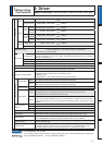
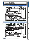
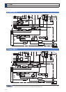
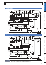
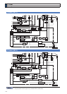
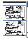
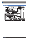
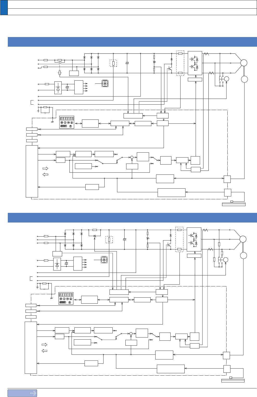
2. Driver
Block Diagram
Note
7KHÀJXUHDERYHVKRZVFRQQHFWLRQVRQYHORFLW\SRVLWLRQWRUTXHDQGIXOOFORVHGPRGHGULYHU
Only for position control type is not provided with X2, X3 and X5.