


2-53
1
Before Using the Products
2
Preparation
3
Connection
4
Setup
5
Adjustment
6
When in Trouble
7
Supplement
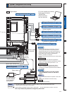
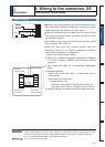
A safety by-pass plug is supplied as standard equipment. Do not disconnect it in normal
times.
When controlling the safety function from the connected host controller, accessory con-
QHFWRUFDQQRWEHXVHG3UHSDUHDQGZLUHWKHFRQQHFWRURSWLRQDVVSHFLÀHGEHORZ
Since the standard connector cannot be used when controlling the safety function from
the host controller, purchase the optional connector and make connection as shown be-
low.
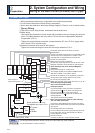
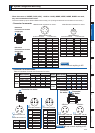
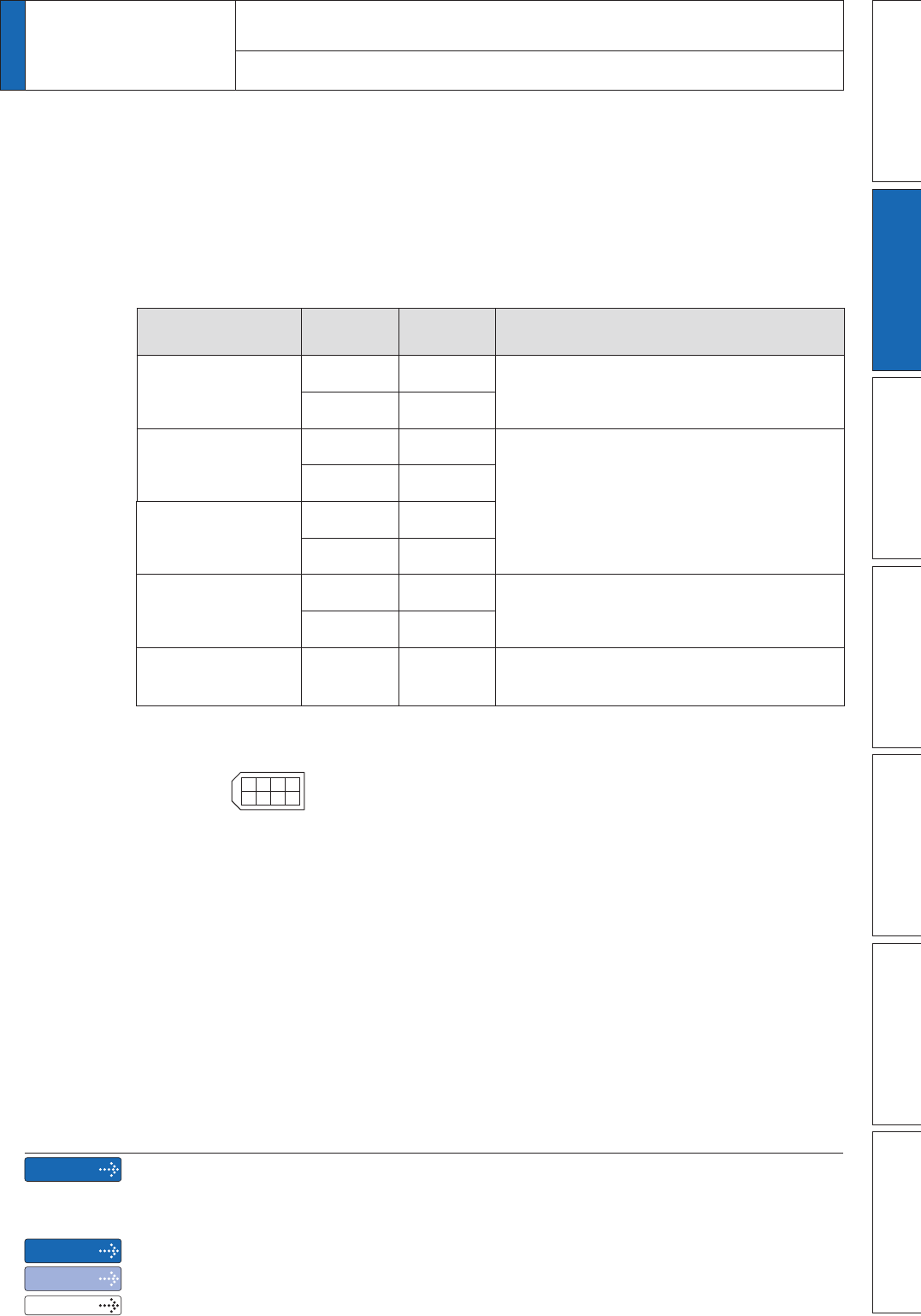
Application Symbol
Connector
Pin No.
Contents
NC
–1
Do not connect.
–2
Safety input 1
SF1ï 3
These are two independent circuits that
turn off the operation signal to the power
module to shut off the motor current.
SF1+ 4
Safety input 2
SF2ï 5
SF2+ 6
EDM output
EDMï 7
This is an output for monitoring the failure
of the safety function.
EDM+ 8
Frame ground FG Shell
Connected with protective earth terminal in
the servo driver.
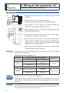
Connector (plug): 2013595-1 (optional, available from Tyco Electronics)
8642
7531
[Connector pin assignment]
(Viewed from cable)
2
Preparation
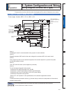
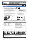
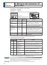
5. Wiring to the connector, X3
Safety function connector
Remarks
Caution
Note
Related page
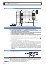
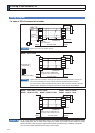
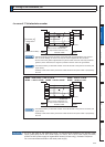
;WR;DUHXVHGIRUWKHVHFRQGDU\FLUFXLW7RFRQQHFWWKHVHWHUPLQDOVWRWKHSULPDU\SRZHU
supply (particularly, the 24 VDC power supply for control, the 24 VDC power supply for brake,
and the 24 VDC power supply for regenerative resistor [H-frame only]), insulation is required.
Do not connect these terminals to the same power supply.
'LVFRQQHFWLQJWKLVFRQQHFWRUGXULQJRSHUDWLRQUHVXOWVLQLPPHGLDWHVWRS
2QO\IRUSRVLWLRQFRQWUROW\SHLVQRWSURYLGHGZLWK;
3´&RQQHFWRU.LWIRU6DIHW\µ