


6-24
6
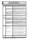
3. Troubleshooting
When in Trouble
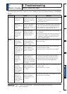
Positioning Accuracy Is Poor
&ODVVLÀFDWLRQ
Causes Measures
System
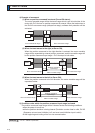
Position command is not correct.
(Amount of command pulse)
Count the feedback pulses with a monitor function of the
PANATERM or feedback pulse monitor mode of the console while
repeating the movement of the same distance. If the value does
not return to the same value, review the controller. Make a noise
measure to command pulse.
Captures the positioning
complete signal at the edge.
Monitor the deviation at positioning complete signal reception
ZLWKWKH&RQQHFWRU;RUWKHZDYHIRUPJUDSKLFIXQFWLRQRIWKH
PANATERM.
Make the controller capture the signal not at the edge but with
some time allowance.
Shape or width of the
command pulse is not per the
VSHFLÀFDWLRQV
If the shape of the command pulse is broken or narrowed, review
the pulse generating circuit. Make a noise measure.
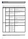
Noise is superposed on
deviation counter clear input CL
&RQQHFWRU;3LQ
Make a noise measure to external DC power supply and make no
wiring of the unused signal lines.
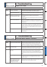
Adjustment
Position loop gain is small. Check the position deviation with the monitor function of the
PANATERM or at the monitor mode of the console.
,QFUHDVHWKHVHWXSRI3UZLWKLQWKHUDQJHZKHUHQRRVFLOODWLRQ
occurs.
Parameter
Setup of the positioning
complete range is large.
Lower the setup of Pr4.31 within the range where no chattering of
complete signal occurs.
Command pulse frequency have
H[FHHGHGNSSVRU0SSV
Lower the command pulse frequency. Change the division/
multiplication ratio of 1st and 2nd numerator of command division/
PXOWLSOLFDWLRQ3UDQG3U8VHDSXOVHOLQHLQWHUIDFH
exclusive to line driver when pulse line interface is used.
Setup of the division/
multiplication is not correct.
Check if the repetition accuracy is same or not. If it does not
change, use a larger capacity motor and driver.
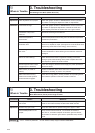
Velocity loop gain is proportion
action at motor in stall.
6HWXS3UDQG3URIWLPHFRQVWDQWRIYHORFLW\ORRS
LQWHJUDWLRQWRRUVPDOOHU
5HYLHZWKHZLULQJDQGFRQQHFWLRQVRWKDWWKHFRQQHFWLRQEHWZHHQ
Pin-27 and 41 of the gain switching input connector, Connector
;EHFRPHVRIIZKLOH\RXVHWXS3URIQGJDLQVHWXSWR
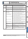
Wiring
Each input signal of Connector
;LVFKDWWHULQJ
1) Servo-ON signal
2) Deviation counter clear input
signal
3) Positive/Negative direction
torque limit input signal
4) Command pulse inhibition
input
&KHFNWKHZLULQJDQGFRQQHFWLRQEHWZHHQ3LQDQGRIWKH
FRQQHFWRU&RQQHFWRU;XVLQJWKHGLVSOD\IXQFWLRQRI,2VLJQDO
status. Correct the wiring and connection so that the servo-On
signal can be turned on normally. Review the controller.
&KHFNWKHZLULQJDQGFRQQHFWLRQEHWZHHQ3LQDQGRIWKH
FRQQHFWRU&RQQHFWRU;XVLQJGLVSOD\IXQFWLRQRI,2VLJQDO
status. Correct the wiring and connection so that the deviation
counter clear input can be turned on normally. Review the
controller.
3 Check the wiring and connection between Pin-18 and 17, 16 and
RIWKHFRQQHFWRU&RQQHFWRU;XVLQJWHVWHURURVFLOORVFRSH
Correct the wiring and connection so that Positive/Negative
direction torque limit input can be entered normally.
4) Check the wiring and connection between Pin-33 and 41of the
FRQQHFWRU&RQQHFWRU;XVLQJGLVSOD\IXQFWLRQRI,2VLJQDO
status. Correct the wiring and connection so that the command
pulse inhibition input can be entered normally. Review the controller.
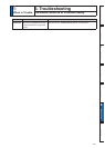
Installation
Load inertia is large. Check the overshoot at stopping with graphic function of the
PANATERM. If no improvement is obtained, increase the driver and
motor capacity.
Related page
3´'HWDLOVRISDUDPHWHUµ3´,QSXWVDQGRXWSXWVRQFRQQHFWRU;µ
3´2XWOLQHRI6HWXSVXSSRUWVRIWZDUH´3$1$7(50µ