


2-50
)ROORZWKHSURFHGXUHVEHORZIRUWKHZLULQJFRQQHFWLRQWRWKH&RQQHFWRU
XA
,
XB
and
XC
.
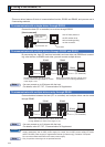
How to connect
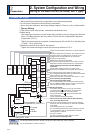
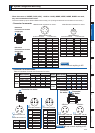
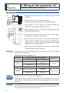
1. Peel off the insulation cover of the cable.
)RUVLQJOHZLUH3OHDVHREH\WKHOHQJWKLQÀJXUH
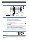
)RUVWUDQGHGZLUHVIHUUXOHVPXVWEHXVHGDVLOOXVWUDWHGEHORZ
Example: Ferrules with plastic insulating sleeve
(AI series, Phoenix Contact, Ltd.)
1) Peel off the sheath so that the conductor portion of the
cable will protrude from the tip of the ferrule. (It should
protrude 1 mm or more from the ferrule.)
2) Insert the cable into the ferrule and crimp it with an ap-
propriate crimping tool.
3) After crimping, cut off the cable conductor portion pro-
truding from the ferrule. (The allowable protruding length
after cutting should be 0 to 0.5 mm.)
Part No. of the crimping tool:
CRIMPFOX U-D66 (1204436)
Available from Phoenix Contact, Ltd.
(1)
(2)
(3)
1mm or more
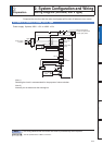
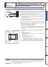
Examples: Nylon-insulated ferrule
(NTUB series, J.S.T. Mfg. Co., Ltd.)
Vinyl-insulated ferrule
(VTUB series, J.S.T. Mfg. Co., Ltd.)
1) Peel off the sheath of the cable conductor
portion to the length equal to that of sheath
on the ferrule.
2) Insert the cable into the ferrule and crimp it
with an appropriate crimping tool.
3DUW1RRIWKHFULPSLQJWRRO<17
Available from J.S.T. Mfg. Co., Ltd
:KHQSHHOLQJRIIWKHVKHDWKRIWKHFDEOHWDNHFDUHQRWWRGDPDJHRWKHUSRUWLRQV
:KHQFULPSLQJWKHIHUUXOHVXIÀFLHQWO\FKHFNWKHVWDWXVRIWKHIHUUXOHDQGFDEOH,IWKHFRQGXFWRUVRIWKHFDEOH
stick out from the insulation cover or protrude excessively from the tip of the ferrule, accidents such as an elec-
WULFVKRFNDQGÀUHIURPDVKRUWFLUFXLWPD\UHVXOW
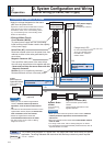
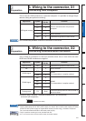
100V/200V specifications
<Cables Compatible with Connector>
Conductor Size AWG18 to 12
6KHDWK2XWOLQH ѮWRѮPP
<Recommended Connector Bar Terminal>
Conductor Size AWG18
7HUPLQDO0RGHO1XPEHU $,*<3KRHQL[&RQWDFW/WG
Conductor Size AWG16 to 14
Terminal Model Number VTUB-2 or NTUB-2 (J.S.T. Mfg. Co., Ltd)
400V specifications
XA, XB, XC
<Cables Compatible with Connector>
Conductor Size AWG18 to 12
6KHDWK2XWOLQH ѮWRѮPP
<Recommended Connector Bar Terminal>
Conductor Size AWG16 to 14
Terminal Model Number VTUB-2 or NTUB-2 (J.S.T. Mfg. Co., Ltd)
XD
<Cables Compatible with Connector>
Conductor Size AWG24 to 20
6KHDWK2XWOLQH ѮWRѮPP
<Recommended Connector Bar Terminal>
Conductor Size AWG24 to 22
Terminal Model Number VTUB-0.5 (J.S.T. Mfg. Co., Ltd)
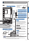
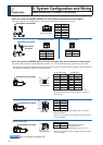
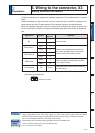
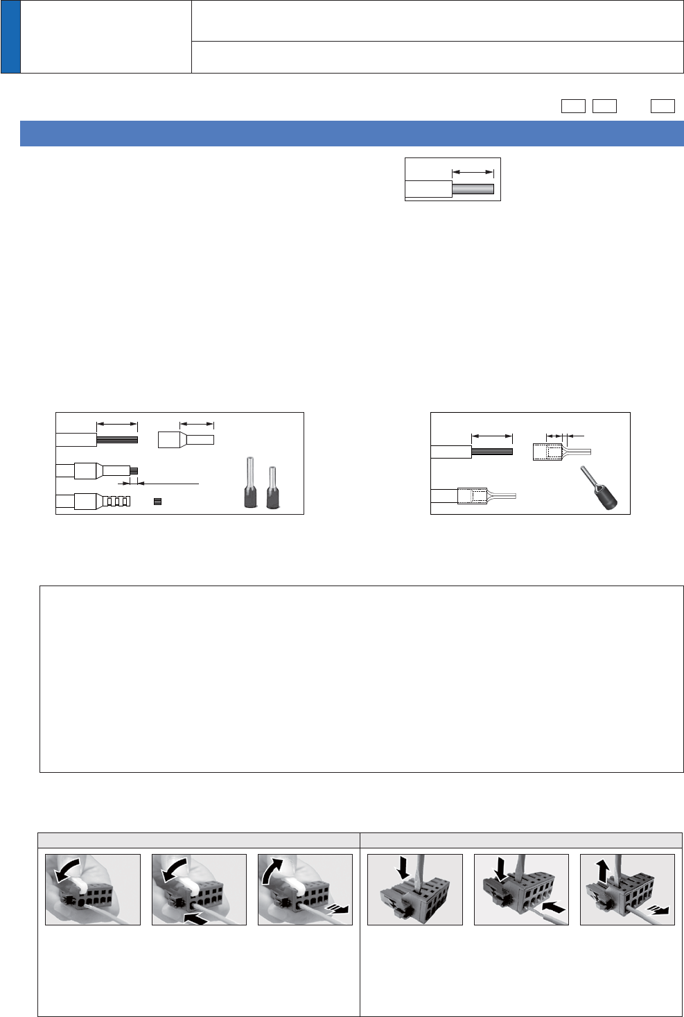
2. Insert the cable to the connector in the following 2 methods.
(a) Insert the cable using the supplied handle lever.
E,QVHUWWKHFDEOHXVLQJDÁDWEODGHVFUHZGULYHU(GJHZLGWKWRPP
Attach the handle
lever to the handling
slot on the upper
portion. Press down
the lever to push
down the spring.
Insert the peeled
cable while pressing
down the lever, until
it hits the insertion
slot (round hole).
Release the lever.
Release the screw
driver.
Press the screw
driver to the
handling slot on the
upper portion to
push down the
spring.
Insert the peeled
cable while pressing
down the screw
driver, until it hits
the insertion slot
(round hole).
(a) Using handle lever (b) Using screw driver
* You can pull out the cable by pushing down the spring as the above.
123 123
7DNHRIIWKHFRQQHFWRUIURPWKH6HUYR'ULYHUEHIRUHPDNLQJFRQQHFWLRQ
,QVHUWRQO\RQHFDEOHLQWRHDFKRQHRIFDEOHLQVHUWLRQVORW
3D\DWWHQWLRQWRLQMXU\E\VFUHZGULYHU
8 to 9 mm
2
Preparation
2.
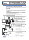
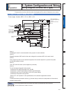
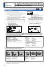
6\VWHP&RQÀJXUDWLRQDQG:LULQJ
Wiring method to connector