


7-122
7
7. Options
Supplement
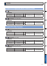
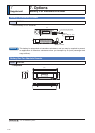
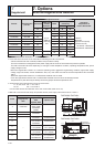
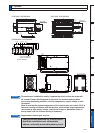
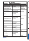
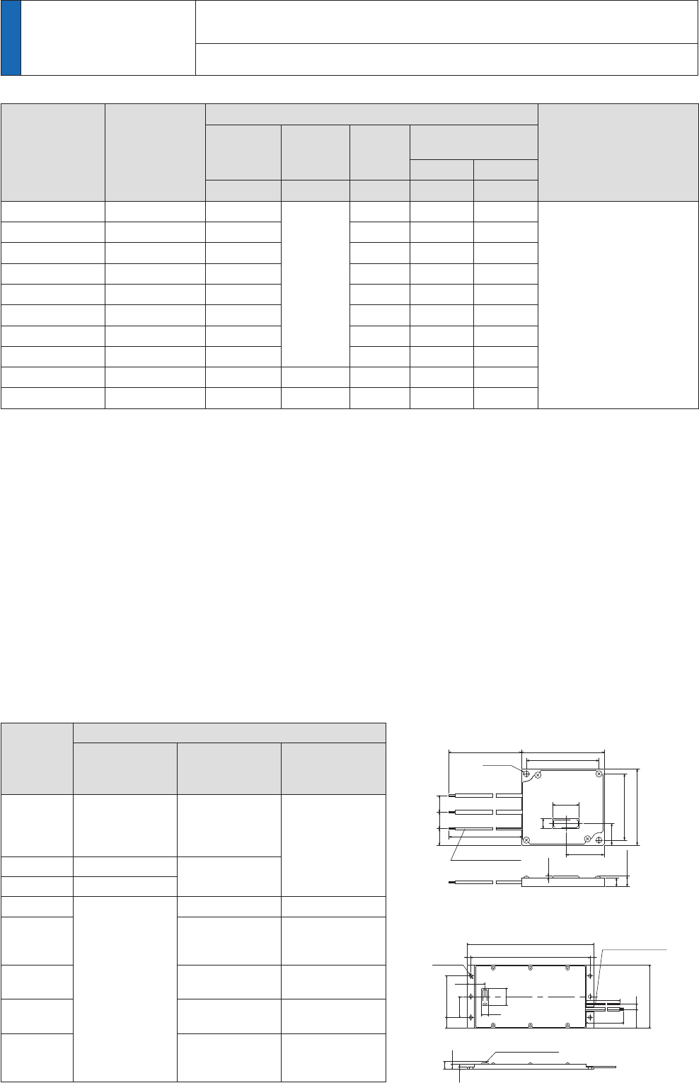
External Regenerative Resistor
DV0P4280, DV0P4281
DV0P4282, DV0P4283
Ѯ
60
30
17
21
8
13
1313
7
10MAX
300
Drawing process
thermostat
(light yellow ×2)
(2mm MAX)
10MAX
7
10
23
170±1
160
28
24
±1
300±30
Ѯ
thermostat
(light yellow ×2)
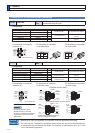
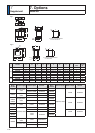
Part No.
Manufacturer's
part No.
Specifications
Activation
temperature of
built-in thermostat
Resistance
cable core
outside
diameter
Mass
Rated power
(reference)
*1
Free air with fan
ї mm kg W W
DV0P4280 RF70M 50
Ѯ
AWG18
stranded
(
wire
)
0.1 10 25
Ý&
B-contact
Open/Close capacity
(resistance load)
1A 125VAC 6000 times
0.5A 250VAC 10000 times
DV0P4281 RF70M 100 0.1 10 25
DV0P4282 RF180B 25 0.4 17 50
DV0P4283 RF180B 50 0.2 17 50
DV0P4284 RF240 30 0.5 40 100
DV0P4285 RH450F 20 1.2 52 130
DV0PM20048 RF240 120 0.5 35 80
DV0PM20049 RH450F 80 1.2 65 190
DV0PM20058 RH450F × 6 3.3 —
*2
16 —
*3
780
DV0PM20059 RH450F × 6 13.3 —
*2
16 —
* 3
1140
Manufacturer : Iwaki Musen Kenkyusho
*1 Power with which the driver can be used without
activating the built-in thermostat.
A built-in thermal fuse and a thermal protector are provided for safety.
The circuit should be so designed that the power supply will be turned off as the thermal protector operates.
The built-in thermal fuse blows depending on changes in heat dissipation condition, operating temperature limit, power
supply voltage or load.
Mount the regenerative resistor on a machine operating under aggressive regenerating condition (high power supply
voltage, large load inertia, shorter deceleration time, etc.) and make sure that the surface temperature will not exceed
100°C.
$WWDFKWKHUHJHQHUDWLYHUHVLVWRUWRDQRQÁDPPDEOHPDWHULDOVXFKDVPHWDO
&RYHUWKHUHJHQHUDWLYHUHVLVWRUZLWKDQRQÁDPPDEOHPDWHULDOVRWKDWLWFDQQRWEHGLUHFWO\WRXFKHG
Temperatures of parts that may be directly touched by people should be kept below 70°C.
*2 Terminal block with screw tightening torque as shown below.
T1, T2, 24V, 0V, E M4 1.2 to 1.4N·m
R1, R2 M5 2.0 to 2.4N·m
8VHWKHFDEOHZLWKWKHVDPHGLDPHWHUDVWKHPDLQFLUFXLWFDEOH5HIHUWR3
*3 With built-in fan which should always be operated with the power supply connected across 24 V and 0 V.
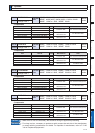
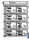
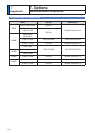
Frame
Power supply
Single phase,
9
Single phase,
9
SKDVH9
SKDVH9
A DV0P4280
DV0P4281
(50W, 100W)
DV0P4283
(200W)
—
B DV0P4283
DV0P4283
C DV0P4282
D
—
DV0P4284 DV0PM20048
E
DV0P4284
× 2 in parallel or
DV0P4285
DV0PM20049
F
DV0P4285
× 2 in parallel
DV0PM20049
× 2 in parallel
G
DV0P4285
× 3 in parallel
DV0PM20049
× 3 in parallel
H
DV0P4285
× 6 in parallel or
DV0PM20058
DV0PM20049
× 6 in parallel or
DV0PM20059