


2-56
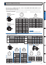
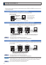
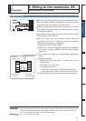
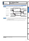
Wiring Diagram of X5
External scale side
External scale unit
Detection head
Junction cable
Servo driver
EX5V
EX0V
EXPS
EXPS
EXA
EXA
EXB
EXB
EXZ
EXZ
EX5V
EX0V
EXPS
EXPS
EXA
EXA
EXB
EXB
EXZ
EXZ
FG
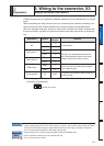
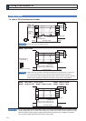
Connector X5
1
2
+5V
0V
3
4
5
6
7
8
9
10
Regulator
Shell of X5 (FG)
MUF-PK10-X
(J.S.T. Mfg. Co., Ltd.)
Twisted pair
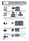
7. Wiring to the connector, X5
Connect on to Feedback Scale
How to Wiring
Wire the signals from the external scale to the external scale connector, X5.
1) Cable for the external scale to be the twisted pair with bundle shielding and to hav-
ing the twisted core wire with diameter of 0.18mm
2
.
2) Cable length to be max. 20m. Double wiring for 5V power supply is recommended
when the wiring length is long to reduce the voltage drop effect.
&RQQHFWWKHRXWHU ÀOPRIWKHVKLHOGZLUHRIWKHH[WHUQDO VFDOHWRWKHVKLHOGRIWKH
MXQFWLRQFDEOH$OVRFRQQHFWWKHRXWHUÀOPRIWKHVKLHOGZLUHWRWKHVKHOO)*RIFRQ-
nector X5 of the driver without fail.
4) Separate the wiring to X7 from the power line (L1, L2, L3, B1, B2, B3, U, V. W,
)
as much as possible (30cm or more). Do not pass these wires in the same duct, nor
bundle together.
5) Do not connect anything to the vacant pins of X5.
6) The maximum power available from the connector X5 is 250 mA at 5 V ±5%. If you
use an external scale requiring more power, you should provide the suitable power
source by yourself. Some external scales need longer initialization period after
SRZHUXS<RXUGHVLJQVKRXOGPHHWWKLVRSHUDWLRQWLPLQJDIWHUSRZHUXS
7) When driving the external scale from an external power supply, keep the EX5V
pin open circuit so that it does not receive any external voltage. Connect the
GND circuit (0 V) to EX0V (connector X5, pin 2) of the driver to eliminate potential
difference.
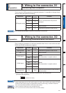
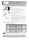
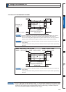
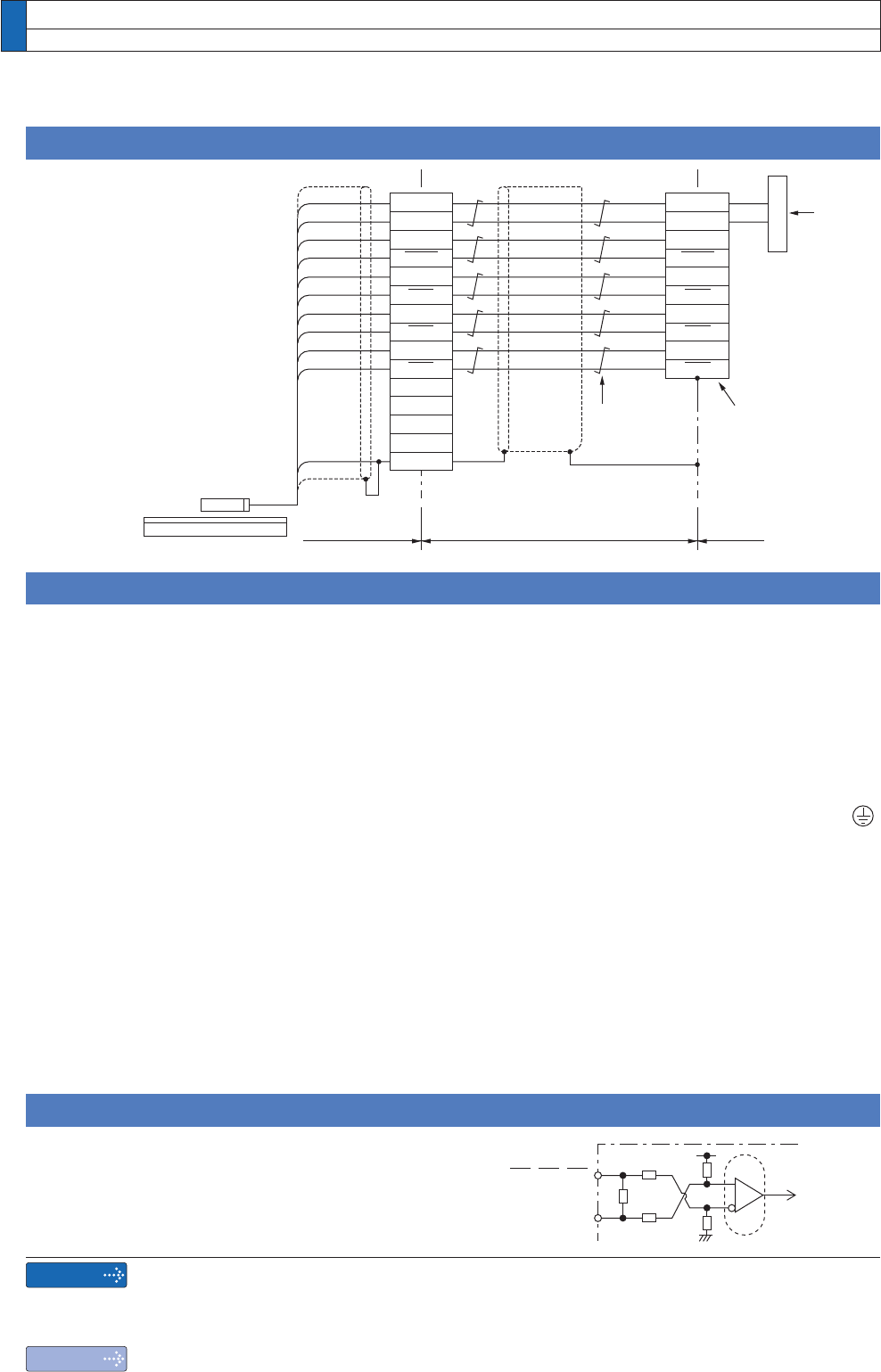
Input circuit
(;$(;%(;=LQSXWFLUFXLW
EXA, EXB, EXZ
EXA, EXB, EXZ
20kї
2kї
2kї
20kї
120ї
PULS
Remarks
Note
;WR;DUHXVHGIRUWKHVHFRQGDU\FLUFXLW7RFRQQHFWWKHVHWHUPLQDOVWRWKHSULPDU\SRZHU
supply (particularly, the 24 VDC power supply for control, the 24 VDC power supply for brake,
and the 24 VDC power supply for regenerative resistor [H-frame only]), insulation is required.
Do not connect these terminals to the same power supply.
2QO\IRUSRVLWLRQFRQWUROW\SHLVQRWSURYLGHGZLWK;