


7-109
1
Before Using the Products
2
Preparation
3
Connection
4
Setup
5
Adjustment
6
When in Trouble
7
Supplement
7
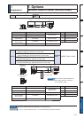
7. Options
Supplement
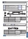
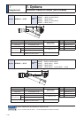
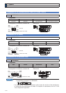
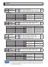
&RQQHFWRU.LW
&RQQHFWRU.LWIRU,QWHUIDFH
Part No.
'93
&RPSRQHQWV
Title Part No.
Number
Manufacturer Note
Connector 10150-3000PE equivalent 1
Sumitomo 3M
*1
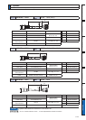
)RU&RQQHFWRU;
(50-pins)
Connector cover 10350-52A0-008 equivalent 1
*1 Old model number: Connector 54306-5019, Connector cover 54331-0501 (Japan Molex Inc.)
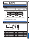
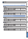
Pin disposition (50 pins) (viewed from the soldering side)
1) Check the stamped pin-No. on the connector body while making a wiring.
2) For the function of each signal title or its symbol, refer to the wiring example of the connector X4.
3)
Do not connect anything to NC pins in the above table.
26
SI3
28
SI5
30
SI7
32
SI9
34
SO2–
36
SO3–
38
SO4–
40
SO6
42
IM
44
PULSH1
46
SIGNH1
48
OB
27
SI4
29
SI6
31
SI8
33
SI10
35
SO2+
37
SO3+
39
SO4+
41
COM
43
SP
45
PULSH2
47
SIGNH2
49
OB
1
OPC1
3
PULS1
5
SIGN1
7
COM
9
SI2
11
SO1+
13
GND
15
GND
17
GND
19
CZ
21
OA
23
OZ
2
OPC2
4
PULS2
6
SIGN2
8
SI1
10
SO1–
12
SO5
14
SPR/
SPL /TRQR
16
P-ATL
18
N-ATL
20
NC
22
OA
24
OZ
50
FG
25
GND
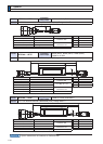
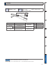
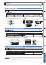
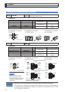
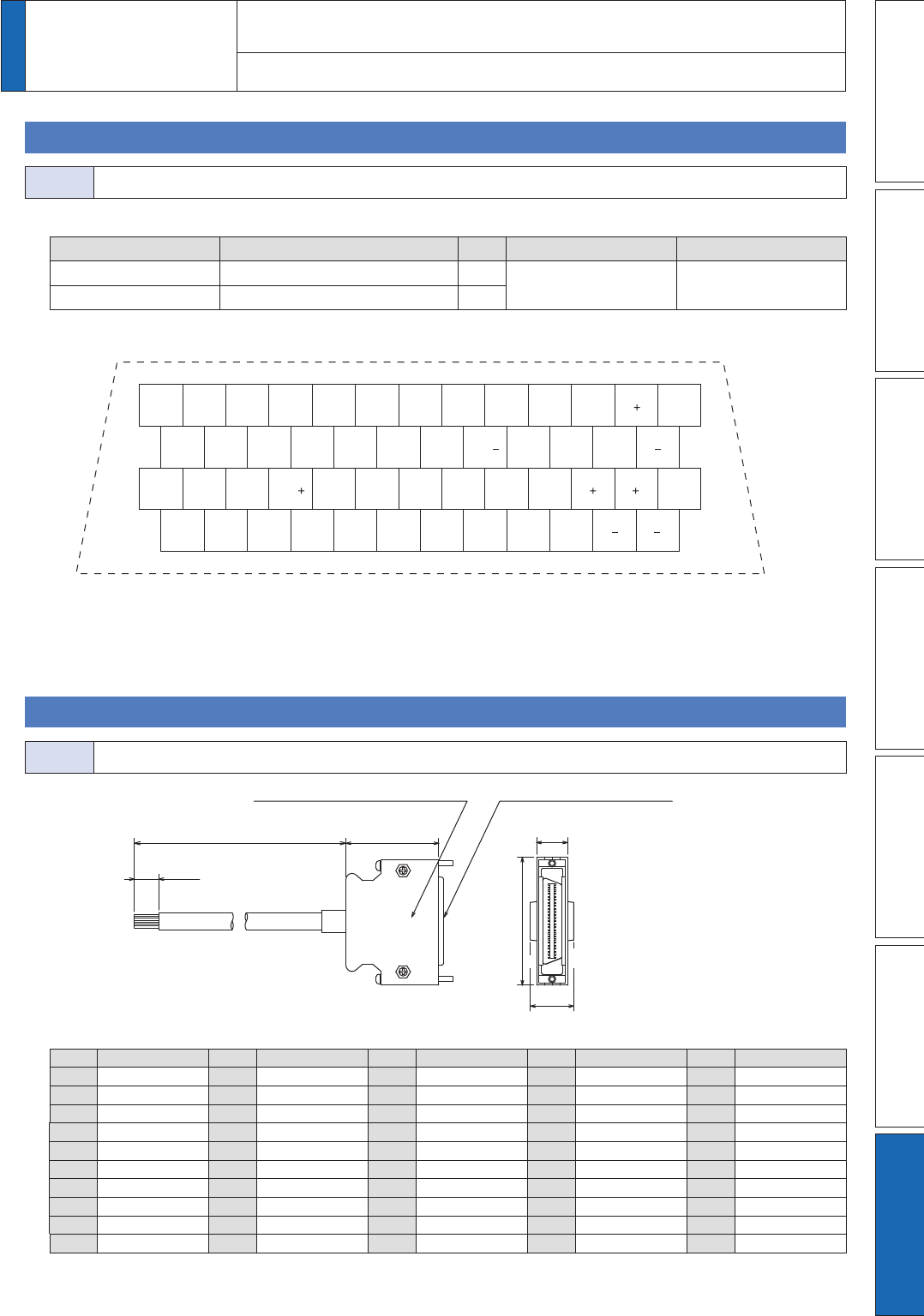
Interface Cable
Part No.
'93
This 2 m connector cable contains AWG28 conductors.
25
50
52.4
2000
+200
0
50
+10
0
39
Connector cover: 10350-52A0-008
Sumitomo 3M or equivalent
Connector: 10150-3000PE
Sumitomo 3M or equivalent
12.7
18
1
26
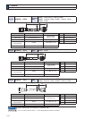
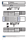
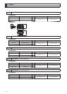
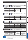
7DEOHIRUZLULQJ
Pin No.
color
Pin No.
color
Pin No.
color
Pin No.
color
Pin No.
color
1 Orange (Red1) 11 Orange (Black2) 21 Orange (Red3) 31 Orange (Red4) 41 Orange (Red5)
2 Orange (Black1) 12 Yellow (Black1) 22 Orange (Black3) 32 Orange (Black4) 42 Orange (Black5)
3 Gray (Red1) 13 Gray (Red2) 23 Gray (Red3) 33 Gray (Red4) 43 Gray (Red5)
4 Gray (Black1) 14 Gray (Black2) 24 Gray (Black3) 34 White (Red4) 44 White (Red5)
5 White (Red1) 15 White (Red2) 25 White (Red3) 35 White (Black4) 45 White (Black5)
6 White (Black1) 16 Yellow (Red2) 26 White (Black3) 36 Yellow (Red4) 46 Yellow (Red5)
7 Yellow (Red1) 17
Yel (Blk2)/Pink (Blk2)
27 Yellow (Red3) 37 Yellow (Black4) 47 Yellow (Black5)
8 Pink (Red1) 18 Pink (Red2) 28 Yellow (Black3) 38 Pink (Red4) 48 Pink (Red5)
9 Pink (Black1) 19 White (Black2) 29 Pink (Red3) 39 Pink (Black4) 49 Pink (Black5)
10 Orange (Red2) 20 – 30 Pink (Black3) 40 Gray (Black4) 50 Gray (Black5)
<Remarks>
Color designation of the cable e.g.) Pin-1 Cable color : Orange (Red1) : One red dot on the cable
The shield of this cable is connected to the connector shell but not to the terminal.