


2-31
1
Before Using the Products
2
Preparation
3
Connection
4
Setup
5
Adjustment
6
When in Trouble
7
Supplement
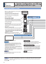
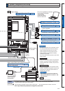
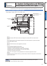
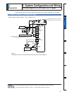
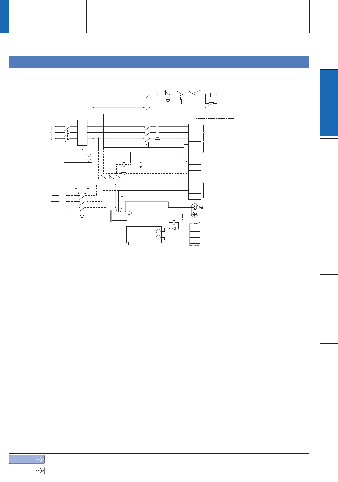
Power supply 3-phase, 200V to 230V–15% +10%
Note 1)
Magnetic contactor MC2 must be the same rating as the contactor MC1 in the main circuit.
Note 2)
Servo may be turned on in the external sequence if the contact deposits: to protect the system,
provide the auxiliary contact.
Note 3)
Use 1.2 ї, 400 W resistor (to be supplied by customer).
Note 4)
To use the external dynamic brake resistor:
Connect the R1 and R2 terminals to B1 and B2.
Connect the T1 and T2 terminals as shown in the left diagram.
Connect the 24 V and 0 V terminals to a 24 VDC power supply.
Connect the E terminal to the ground.
Refer to P.7-122 “Options” for the specifications of the external regenerative resistor.
Note 5)
Provide an external protective device (e.g. thermal fuse) to monitor the temperature of the external
dynamic brake resistor.
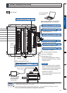
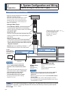
Noise filter
Main power
supply
Control power
supply
Motor
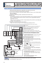
37
ALM
L2
L3
L1C
L2C
MC1
L1
ALM
MCCB
Motor
connection
36
L
ON
ALM
B1
B2
DB1
NC
DB2
U
V
W
ALM
OFF
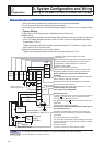
Coil surge suppression units
Built-in thermostat of
an external regenerative resistor
(T1 and T2 terminals)
Note 4)
Power supply
(3-phase)
MC1
Note 1)
Note 4)
R1
R2
Note 5) Note 5) Note 5)
Dynamic Brake resistor
Note 3)
Note 2)
MC2
MC2
Coil surge suppression units
External
regenerative resistor
Insulated
DC12 to 24V
(±5%)
+
ï
Insulated
DC24V
+
ï
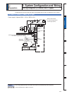
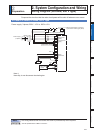
Compose the circuit so that the main circuit power will be shut off when an error occurs.
In Case of 3-Phase, H-frame, 200 V type
2
Preparation
2.
6\VWHP&RQÀJXUDWLRQDQG:LULQJ
Wiring Diagram (H-frame, 200 V type)
Note
Related page
The wiring indicated with the broken line shall be provided only when required.
3´6SHFLÀFDWLRQVRI0RWRUFRQQHFWRUµ