


2-11
1
Before Using the Products
2
Preparation
3
Connection
4
Setup
5
Adjustment
6
When in Trouble
7
Supplement
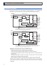
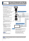
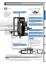
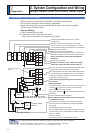
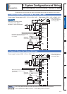
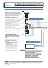
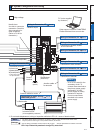
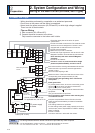
2. 6\VWHP&RQÀJXUDWLRQDQG:LULQJ
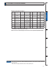
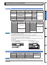
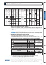
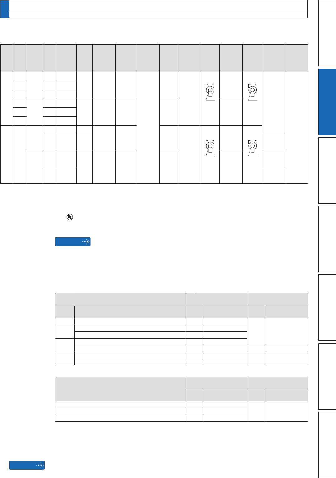
'ULYHUDQG/LVWRI$SSOLFDEOH3HULSKHUDO(TXLSPHQWV
Driver
Applicable
motor
Voltage
*1
Rated
output
5HTXLUHG
Power
at the
(
rated load
)
Circuit
breaker
rated
(
current
)
Noise
ÀOWHU
Surge
absorber
Noise
ÀOWHUIRU
signal
Rated
operating
current of
magnetic
contactor Contact
(
FRQÀJXUDWLRQ
)
*2
Diameter
and
withstand
voltage of
main circuit
cable
Crimp
terminal
for main
circuit
terminal
block
Diameter
and
withstand
voltage
of control
power
supply cable
Crimp
terminal
for control
power
supply
terminal
block
Diameter
and
withstand
voltage of
motor cable
*4
Diameter
and
withstand
voltage of
brake cable
MGDH
MDME
3-phase,
200V
7.5kW
approx.
11kVA
60A
FS5559-60-34
Recommended
(
component
)
DV0P1450
DV0P1460
RJ8095
Recommended
(
component
)
T400-61D
Recommended
(
component
)
*5
100A
3P+1a
5.3mm
2
/
AWG10
600 VAC
or more
11mm or
smaller
ø5.3
Terminal
block
M5
0.75mm
2
/
AWG18
600 VAC
or more
10mm or
smaller
ø5.3
Terminal
block
M5
13.3 mm
2
/
AWG6
600 VAC
or more
0.75mm
2
/
AWG18
100 VAC
or more
MGME 6.0kW
approx.
9.0kVA
MHME 7.5kW
approx.
11kVA
MDME
3-phase,
400V
7.5kW
approx.
11kVA
30A
FN258-42-07
FN258-42-33
Recommended
(
component
)
DV0PM20050
60A
3P+1a
0.75mm
2
/
AWG18
100 VAC
or more
MGME 6.0kW
approx.
9.0kVA
MHME 7.5kW
approx.
11kVA
MHDH MDME
3-phase,
200V
11kW
approx.
17kVA
100A
FS5559-80-34
Recommended
(
component
)
DV0P1450
150A
3P+1a
13.3mm
2
/
AWG6
600 VAC
or more
*3
16mm or
smaller
ø6.4
Terminal
block
M6
0.75mm
2
/
AWG18
600 VAC
or more
10mm or
smaller
ø4.3
Terminal
block
M4
15kW
approx.
22kVA
125A
21.1 mm
2
/
AWG4
600 VAC
or more
3-phase,
400V
11kW
approx.
17kVA
50A
FN258-42-07
FN258-42-33
Recommended
(
component
)
DV0PM20050
100A
3P+1a
0.75mm
2
/
AWG18
100 VAC
or more
13.3 mm
2
/
AWG6
600 VAC
or more
15kW
approx.
22kVA
60A
21.1 mm
2
/
AWG4
600 VAC
or more
Remarks
$ERXWFLUFXLWEUHDNHUDQGPDJQHWLFFRQWDFWRU
7RFRPSO\WR (&'LUHFWLYHVLQVWDOOD FLUFXLWEUHDNHUEHWZHHQ WKHSRZHUDQGWKH QRLVHÀOWHU
without fail, and the circuit breaker should conform to IEC Standards and UL recognized (Listed
and
marked).
Suitable for use on a circuit capable of delivering not more than 5,000Arms symmetrical amperes, be-
low the maximum input voltage of the product.
Remarks
6HOHFWDFLUFXLWEUHDNHUDQGQRLVHÀOWHUZKLFKPDWFKWRWKHFDSDFLW\RISRZHU
supply (including a load condition).
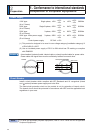
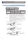
Terminal block and protective ground terminals
8VHDFRSSHUFRQGXFWRUFDEOHVZLWKWHPSHUDWXUHUDWLQJRIÝ&RUKLJKHU
8VHWKHDWWDFKHGH[FOXVLYHFRQQHFWRUIRU$WR(IUDPHDQGPDLQWDLQWKHSHHOHGRIIOHQJWKRIWR
9mm. (Refer to P.2-50)
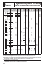
)DVWHQLQJWRUTXHOLVW7HUPLQDOEORFNVFUHZ7HUPLQDOFRYHUIDVWHQLQJVFUHZ
Driver Terminal block screw
Terminal cover fastening
screw
Frame
Terminal name
Nominal
size
)DVWHQLQJWRUTXH
1P
*1
Nominal
size
)DVWHQLQJWRUTXH
1P
*1
F200V L1, L2, , L1C, L2C, B1, B2, B3, NC, U, V, W M5 1.0 to 1.7
M3 0.19 to 0.21F400V
24V 0V M3 0.4 to 0.6
L1, L2, , B1, B2, B3, NC, U, V, W M4 0.7 to 1.0
G
L1C, L2C, 24V, 0V, DB1, DB2, DB3, DB4, NC M5 1.0 to 1.7
L1, L2, , B1, B2, NC, U, V, W M5 2.0 to 2.4 M3 0.3 to 0.5
H
L1C, L2C, 24V, 0V, DB1, DB2 M4 0.7 to 1.0
M5 2.0 to 2.5
L1, L2, , B1, B2, NC, U, V, W M6 2.2 to 2.5
)DVWHQLQJWRUTXHOLVW*URXQGWHUPLQDOVFUHZ&RQQHFWRUWRKRVWFRQWUROOHU;
Driver frame
Terminal block screw
Connector to host
controller (X4)
Nominal
size
)DVWHQLQJWRUTXH
1P
*1
Nominal
size
)DVWHQLQJWRUTXH
1P
*1
A to E M4 0.7 to 0.8
M2.6 0.3 to 0.35F, G M5 1.4 to 1.6
H M6 2.4 to 2.6
*1
Applying fastening torque larger than the maximum value may result in damage to the product.
'RQRWWXUQRQSRZHUZLWKRXWWLJKWHQLQJDOOWHUPLQDOEORFNVFUHZVSURSHUO\
'RQRWWXUQRQSRZHU ZLWKRXWWLJKWHQLQJDOOWHUPLQDOEORFNVFUHZV SURSHUO\RWKHUZLVH
ORRVHFRQWDFWVPD\JHQHUDWHKHDWVPRNLQJÀULQJ
7RFKHFNIRUORRVHQHVVFRQGXFWSHULRGLFLQVSHFWLRQRIIDVWHQLQJWRUTXHRQFHD\HDU
Be sure to conduct wiring properly and securely. Insecure or improper wiring may cause the motor
running out of control or being damaged from overheating. In addition, pay attention not to allow
conductive materials, such as wire chips, entering the driver during the installation and wiring.