


2-78
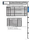
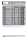
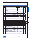
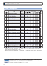
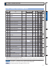
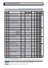
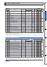
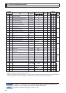
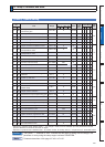
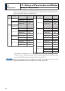
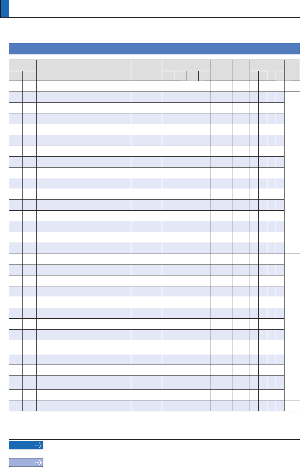
[Class 4] I/F monitor setting
Parametr
No.
Title Range
Default
Unit
Turning
on of
power
supply
Related
Control Mode Detail
page
Class
No.
A,B
-frame
C
-frame
D,E,F
-frame
G,H
-frame
PSTF
4 00 SI1 input selection (Pin No.8)
0 to 00FFFFFFh
8553090 ï
4-33
4 01 SI2 input selection (Pin No.9)
0 to 00FFFFFFh
8487297 ï
4-34
4 02 SI3 input selection (Pin No.26)
0 to 00FFFFFFh
9539850 ï
4 03 SI4 input selection (Pin No.27)
0 to 00FFFFFFh
394758 ï
4 04 SI5 input selection (Pin No.28)
0 to 00FFFFFFh
4108 ï
4 05 SI6 input selection (Pin No.29)
0 to 00FFFFFFh
197379 ï
4 06 SI7 input selection (Pin No.30)
0 to 00FFFFFFh
3847 ï
4 07 SI8 input selection (Pin No.31)
0 to 00FFFFFFh
263172 ï
4 08 SI9 input selection (Pin No.32)
0 to 00FFFFFFh
328965 ï
4 09 SI10 input selection (Pin No.33)
0 to 00FFFFFFh
3720 ï
4 10 SO1 output selection
Pin No.10, 11
(
Line driver output
)
0 to 00FFFFFFh
197379 ï
4-35
4 11 SO2 output selection
Pin No.34, 35
(
Line driver output
)
0 to 00FFFFFFh
131586 ï
4 12 SO3 output selection
Pin No.36, 37
(
Line driver output
)
0 to 00FFFFFFh
65793 ï
4 13 SO4 output selection
Pin No.38, 39
(
Line driver output
)
0 to 00FFFFFFh
328964 ï
4 14 SO5 output selection
Pin No.12
(
Open collector output
)
0 to 00FFFFFFh
460551 ï
4 15 SO6 output selection
Pin No.40
(
Open collector output
)
0 to 00FFFFFFh
394758 ï
4 16 Type of analog monitor 1 0 to 21
0
ï
4-36
4 17 Analog monitor 1 output gain
0 to 214748364
0
ï
4 18 Type of analog monitor 2 0 to 21
4
ï
4 19 Analog monitor 2 output gain
0 to 214748364
0
ï
4 20 Type of digital monitor 0 to 3
0
ï
4 21 Analog monitor output setup 0 to 2
0
ï
4-38
4 22 Analog input 1 (AI1) offset setup
ïWR
0
0.366mV
423$QDORJLQSXW$,ÀOWHU 0 to 6400
0
0.01ms
*
424
Analog input 1 (AI1) overvoltage
setup
0 to 100
0
0.1V
*
4 25 Analog input 2 (AI2) offset setup
ïWR
0
5.86mV
426$QDORJLQSXW$,ÀOWHU 0 to 6400
0
0.01ms
*
427
Analog input 2(AI2) overvoltage
setup
0 to 100
0
0.1V
*
4 28 Analog input 3 (AI3) offset setup
ïWR
0
5.86mV
429$QDORJLQSXW$,ÀOWHU 0 to 6400 0 0.01ms
*
4-39
'HÀQLWLRQRIV\PEROVXQGHU´3RZHU2II2QµLIDFKDQJHLVPDGHLWZLOOEHUHÁHFWHGXSRQWKHSDUDPHWHUZKHQWKH
power to the driver is turned off and then on again.
*
'HÀQLWLRQRIV\PEROVXQGHU´5HODWHGPRGHµ3SRVLWLRQFRQWURO6YHORFLW\FRQWURO7WRUTXHFRQWURO)IXOOFORVHGFRQWURO
13.
Setup of Parameter and Mode
List of Parameters
Caution
Note
The symbol “
*
” attached to “Unit”. indicates that the digits of setting unit will change if the
parameter is set by using the setup support software PANATERM.
Parameter describes of this page is P.4-33 to P.4-39.