


7-3
1
Before Using the Products
2
Preparation
3
Connection
4
Setup
5
Adjustment
6
When in Trouble
7
Supplement
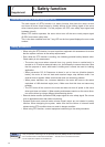
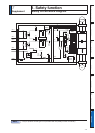
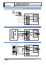
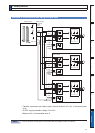
Safety input signal
Caution
For list of connector pin numbers, refer to P.2-53,
Signal Symbol Pin No. Contents
Control
mode
Safety
input 1
SF1+ 4
Input 1 that triggers STO function. This input turns
off the upper arm drive signal of power transistor.
When using the function, connect this pin in a way
so that the photocoupler of this input circuit turns off
to activate STO function.
Compatible
all control
mode
6)ï 3
Safety
input 2
SF2+ 6
Input 2 that triggers STO function. This input turns
off the lower arm drive signal of power transistor.
When using the function, connect this pin in a way
so that the photocoupler of this input circuit turns off
to activate STO function.
6)ï 5
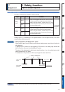
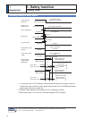
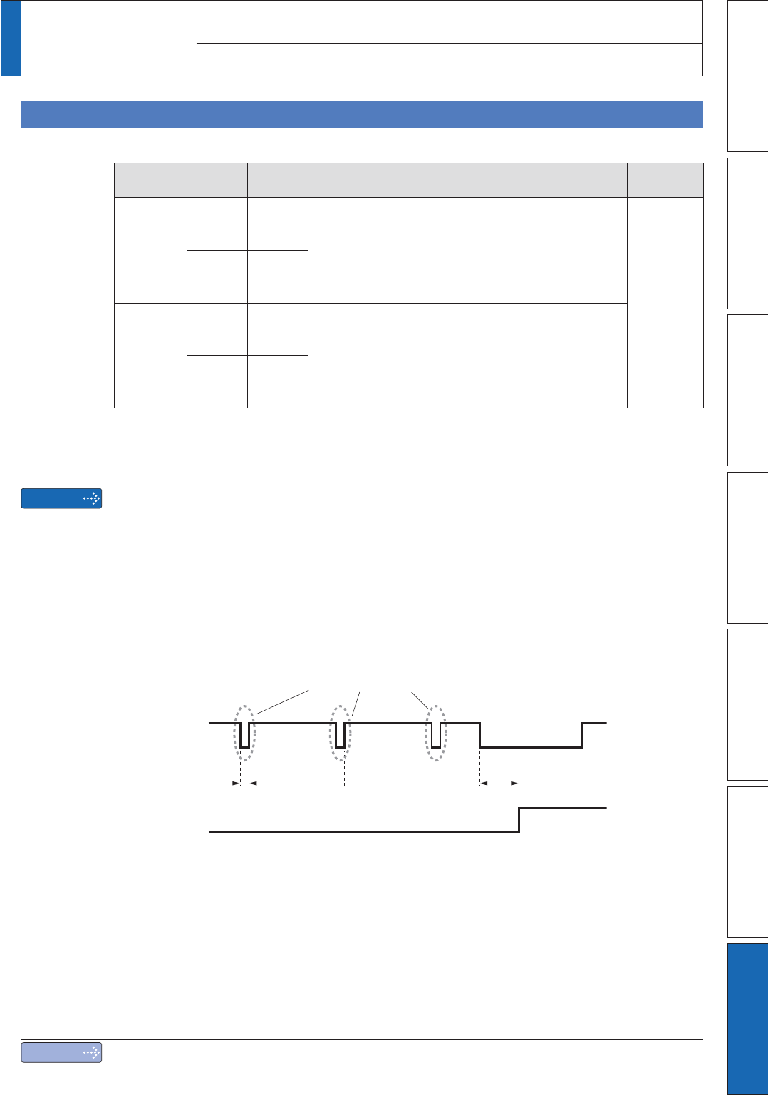
<Response time>
Safety input 1 or 2 enables STO to operate: within 5 ms of response time, the motor
output torque will be turned off.
6DIHW\HTXLSPHQWVHOIGLDJQRVLV/SXOVH
Safety output signal from the safety controller and safety sensor may include L pulse for
self-diagnosis.
To prevent the L pulse from mis-triggering STO function, the safety input circuit has
EXLOWLQÀOWHUWKDWUHPRYHVWKHVHOIGLDJQRVLV/SXOVH
Therefore, if the off period of safety input signal less than 1 ms, the safety input circuit
GRHVQRWGHWHFWWKLV´RIIµHYHQW
7RYDOLGDWHWKLV´RIIµSHULRGWXUQRIIWKHLQSXWVLJQDOIRUPRUHWKDQPV
Safety input
signal
Servo driver
Operate
L pulse for self-diagnosis
1 ms or shorter 5 ms or shorter
Response time
5 ms or more
STO state
7
1. Safety function
Supplement
Input & output signals
Note
2QO\IRUSRVLWLRQFRQWUROW\SHLVQRWSURYLGHGZLWK;6DIHW\IXQFWLRQFRQQHFWRU