


3-14
3
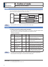
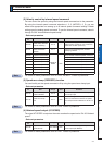
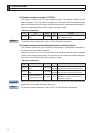
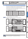
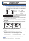
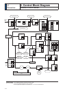
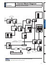
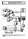
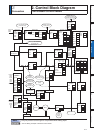
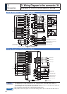
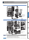
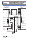
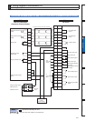
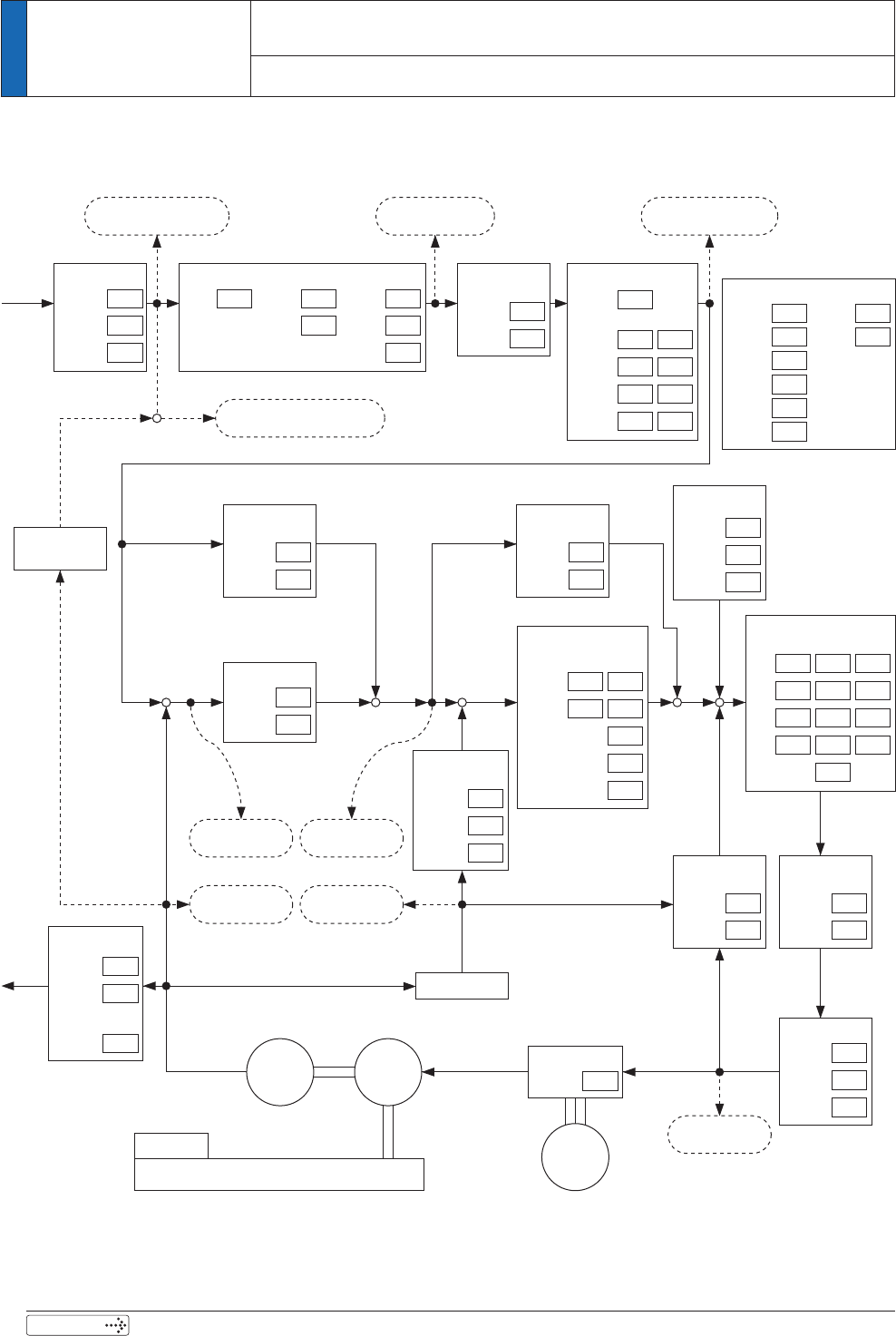
2. Control Block Diagram
Connection
Position Control Mode
Pulse train
PULS
SIGN
Input setup
Sum of command pulses
[Command unit]
Input
selection
Direction
setup
Mode
Notch filter
1st
Frequency
Depth
2nd
Width
3rd
4th
Adaptive
mode setup
Velocity control
1st
Propor-
tion
Integra-
tion
2nd
Inertia ratio
Function
expansion
2nd inertia ratio
Damping control
1st
Switching
selection
Frequency
Filter
2nd
3rd
4th
Smoothing
filter
Electric gear
One
revolu-
tion
1st
numerator
Denominator
Gain switching
2nd
setup
Mode
Delay
time
Level
Hysteresis
Switching
time
3rd
setup
Scale
factor
2nd
numerator
3rd
numerator
Primary
delay
Motor
Load
Main
power
supply
Encoder
Velocity
feed forward
Gain
Filter
Torque
feed forward
Gain
Filter
Position control
1st
2nd
Current control
Speed detection
Response
setup
Torque filter
1st
2nd
Disturbance
observer
Gain
Filter
Speed detection
filter
1st
2nd
Instantaneous
speed
Torque limit
Selection
1st
2nd
Pulse
regeneration
Pulses
output
OA
OB
OZ
Numerator/
Denominator
One
revolution
Reversal
Denomi-
nator
4th
numerator
Command positional deviation
[Command unit]
Encoder
positional deviation
[Encoder pulse]
velocity control
command [r/min]
Torque command
Sum of
feedback pulses
[Encoder pulse]
Motor speed
[r/min]
Inversion of
electric gear
Friction
compensation
additional
value
Positive
direction
Negative
direction
Positional command
speed [r/min]
Internal positional
command speed [r/min]
5HODWHGSDJH
3´:LULQJH[DPSOHRISRVLWLRQFRQWUROPRGHµ
3´&RQQHFWLQJH[DPSOHWRKRVWFRQWUROOHUµ
3´,QSXWVDQGRXWSXWVRQFRQQHFWRU;µ3´/LVWRI3DUDPHWHUVµ