


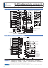
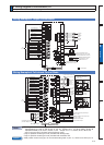
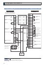
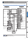
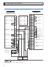
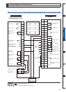
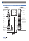
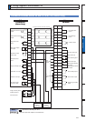
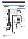
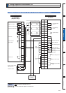
3-26
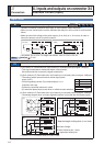
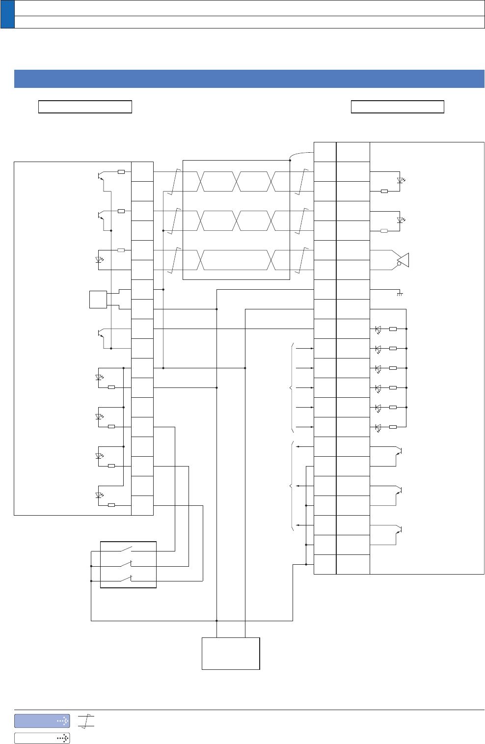
3. Wiring Diagram to the connector, X4
Connecting Example to Host Controller
Connection between MINAS A5 and CJ1W-NC113 (Omron Corp.)
Note
5HODWHGSDJH
UHSUHVHQWVWZLVWHGSDLUZLUH
3´,QSXWVDQGRXWSXWVRQFRQQHFWRU;µ
A5-seriesCJ1W-NC113
(Omron Corp.)
from
PLC I/O
output
to
PLC I/O
input
GND
+ 24V
DC24V
Power supply
Command
pulse
input 2
Counter clear input
Servo-ON input
Servo-Ready output
Servo-Alarm
output
Positioning complete
output
Alarm clear input
Inhibit negative direction
travel input
Inhibit positive direction
travel input
Z-phase output
Command sign
input 2
Gain switching input
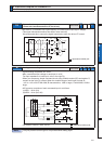
DriverPLC
CCW limit sensor
Origin proximity sensor
CW limit sensor
CW pulse command
output
CCW pulse command
output
Origin line driver
input
Power supply
for output
Deviation counter
reset output
Emergency stop
input
Origin proximity
input
CCW limit excess
input
CW limit excess
input
* Process of shield wire varies with equipment.