7-19
1
Before Using the Products
2
Preparation
3
Connection
4
Setup
5
Adjustment
6
When in Trouble
7
Supplement
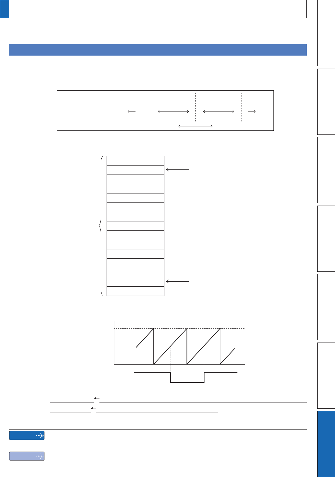
Composition of Absolute Data
Absolute data consists of singe-turn data which shows the absolute position per one
revolution and multi-turn data which counts the number of revolution of the motor after
clearing the encoder.
Single-turn data and multi-turn data are composed by using 15-character data (hexadeci-
mal binary code) which are received via RS232 or RS485.
Single-turn data
CW CCW
–1 0 0 1 1 2
131071 0,1,2 … …13107 1 0,1,2 131071 0,1,
Multi-turn data
Motor rotational direction
'HWDLOVRIPXOWLWXUQGDWD
65535
CW 0 CCW
Error
Absolute counter over
error protection
Normal Error
Multi-turn data
0Bh
Axis address
D2h
03h
11h
Encoder status (L)
Setup value of Pr5.31 “Axis address”.
Encoder status (H)
Single-turn data (L)
Single-turn data (M)
Single-turn data (H)
Multi-turn data (L)
Multi-turn data (H)
00h
Error code
Checksum
Becomes to 0 when the communication is
carried out normally. If not 0, capture the
absolute data from the driver again
Received
absolute data
(15 characters)
Remarks
Note
,IWKH PXOWLWXUQGDWDRIWKHDERYHÀJ LVEHWZHHQ WRFRQYHUW LWWRVLJQHG
date after deducting 65536.
2QO\IRUSRVLWLRQFRQWUROW\SHLVQRWSURYLGHGZLWK;&RPPXQLFDWLRQFRQQHFWRU
2QO\IRUSRVLWLRQFRQWUROW\SHGRHVQRWVXSSRUWWKHELWDEVROXWHVSHFLÀFDWLRQ
,WVXSSRUWVRQO\ELWLQFUHPHQWDOVSHFLÀFDWLRQ
2. Absolute system
Transferring absolute data
Single-turn data Single-turn data (H)×10000h+Single-turn data (M)×100h+Single-turn data (L)
multi-turn data
multi-turn data (H) ×100h+multi-turn data (L)


