


4-3
1
Before Using the Products
2
Preparation
3
Connection
4
Setup
5
Adjustment
6
When in Trouble
7
Supplement
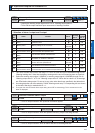
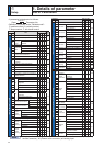
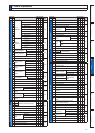
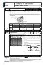
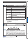
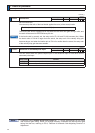
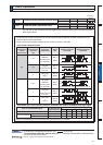
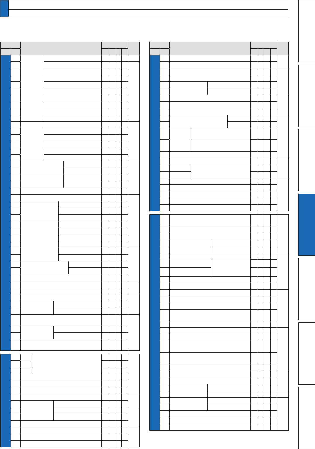
1. Details of parameter
List of Parameters
[Class 4] I/F monitor setting
00
Input
selection
6,3LQ1R
6,3LQ1R
6,3LQ1R
6,3LQ1R
6,3LQ1R
6,3LQ1R
6,3LQ1R
6,3LQ1R
6,3LQ1R
6,3LQ1R
4-33
01
4-34
02
03
04
05
06
07
08
09
10
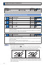
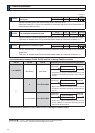
Output
selection
SO1
3LQ1R
/LQHGULYHURXWSXW
SO2
3LQ1R
/LQHGULYHURXWSXW
SO3
3LQ1R
/LQHGULYHURXWSXW
SO4
3LQ1R
/LQHGULYHURXWSXW
SO5
3LQ1R
Open collector output
SO6
3LQ1R
Open collector output
4-35
11
12
13
14
15
16
$QDORJPRQLWRU
type
output gain
4-36
17
18
$QDORJPRQLWRU
type
output gain
19
20 Type of digital monitor
21 $QDORJPRQLWRURXWSXWVHWXS
4-38
22
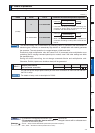
$QDORJLQSXW
$,
offset setup
ÀOWHU
RYHUYROWDJHVHWXS
23
24
25
$QDORJLQSXW
$,
offset setup
ÀOWHU
RYHUYROWDJHVHWXS
26
27
28
$QDORJLQSXW
$,
offset setup
ÀOWHU
RYHUYROWDJHVHWXS
29
4-39
30
31
Positioning complete
,QSRVLWLRQ
range
output setup
32
33 ,13KROGWLPH
34 Zero-speed
4-40
35 Speed coincidence range
36 $WVSHHG6SHHGDUULYDO
4-41
37
Mechanical
brake action
at stalling setup
at running setup
38
39
Mechanical brake action at running
setup
4-42
40
Selection of
alarm output
1
2
41
42
QG3RVLWLRQLQJFRPSOHWH,QSRVLWLRQ
range
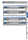
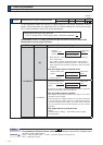
[Class 5] Enhancing setting
00
2nd
numerator of electronic gear
3rd
4th
4-43
01
02
03 'HQRPLQDWRURISXOVHRXWSXWGLYLVLRQ
04 2YHUWUDYHOLQKLELWLQSXWVHWXS
05 6HTXHQFHDWRYHUWUDYHOLQKLELW
06 6HTXHQFHDW6HUYR2II
4-44
07
PDLQSRZHU
OFF
sequence
LV trip selection
detection time
08
4-45
09
10 Sequence at alarm
11 Torque setup for emergency stop
4-46
12 2YHUORDGOHYHOVHWXS
13 2YHUVSHHGOHYHOVHWXS
[Class 5] Enhancing setting
14 0RWRUZRUNLQJUDQJHVHWXS
4-46
15 ,)UHDGLQJÀOWHU
16 $ODUPFOHDULQSXWVHWXS
4-47
17 Counter clear input mode
18
Command pulse
inhibit input
,QYDOLGDWLRQ
reading setup
19
20 Position setup unit select
4-48
21 Selection of torque limit
22 2nd torque limit
23
7RUTXHOLPLWVZLWFKLQJ
setup
1
2
4-49
24
25
([WHUQDO
input
SRVLWLYHGLUHFWLRQWRUTXH
limit
QHJDWLYHGLUHFWLRQWRUTXH
limit
26
27 Input gain of analog torque limit
28 LED initial status
4-50
29
RS232
baud rate setup
RS485
30
31 $[LVDGGUHVV
4-51
32
&RPPDQGSXOVHLQSXWPD[LPXPVHWXS
33 3XOVHUHJHQHUDWLYHRXWSXWOLPLWVHWXS
34 For manufacturer's use
35 Front panel lock setup
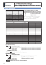
[Class 6] Special setting
00
$QDORJWRUTXHIHHGIRUZDUG
FRQYHUVLRQJDLQ
4-52
02 9HORFLW\GHYLDWLRQH[FHVVVHWXS
04 JOG trial run command speed
05
Position 3rd gain
YDOLGWLPH
scale factor
06
07 7RUTXHFRPPDQGDGGLWLRQDOYDOXH
4-53
08
3RVLWLYHGLUHFWLRQ
torque
compensation
YDOXH
1HJDWLYHGLUHFWLRQ
09
10 )XQFWLRQH[SDQVLRQVHWXS
11 Current response setup
13 2nd Inertia ratio
4-54
14 Emergency stop time at alarm
15 QGRYHUVSHHGOHYHOVHWXS
17
)URQWSDQHOSDUDPHWHUZULWLQJ
selection
18 3RZHUXSZDLWWLPH
19 Encoder Z phase setup
4-55
20 =SKDVHVHWXSRIH[WHUQDOVFDOH
21
6HULDODEVROXWHH[WHUQDOVFDOH=SKDVH
setup
22
$%SKDVHH[WHUQDOVFDOHSXOVH
output method selection
23
Disturbance torque compensating gain
24 'LVWXUEDQFHREVHUYHUÀOWHU
4-56
27 $ODUPODWFKWLPHVHOHFWLRQ
31
Real time
auto tuning
estimation speed
custom setup
32
4-57
34
+\EULGYLEUDWLRQ
suppression
gain
ÀOWHU
4-58
35
37 2VFLOODWLRQGHWHFWLRQOHYHO
38 $ODUPPDVNVHWXS
39 For manufacturer's use
Parametr No.
Title
Related Control Mode
Detail
page
Class No.
PSTF
Parametr No.
Title
Related Control Mode
Detail
page
Class No.
PSTF