


2-68
2
Preparation
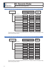
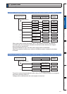
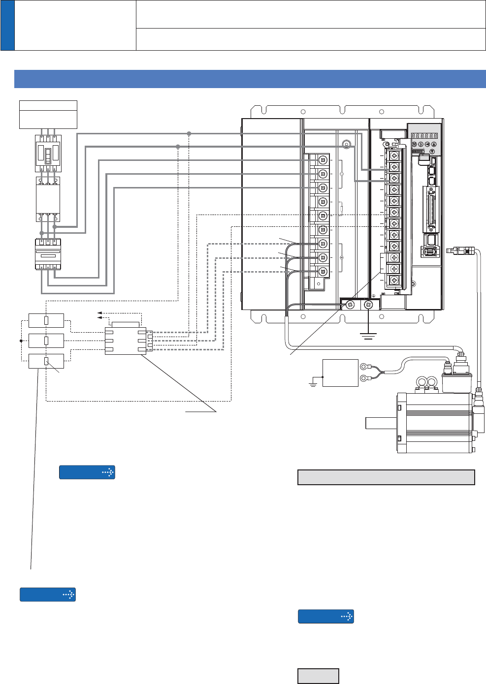
12. Dynamic Brake
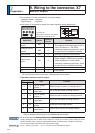
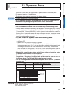
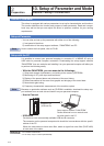
Connections of external dynamic brake resistor (Example)
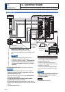
G-frame, 200 V
Remarks
Magnetic Contactor (MC)
Turns on/off the dynamic brake resistor.
Use coil surge suppression units together with
this.
6KRXOGEHWKHVDPHUDWLQJDVWKDWRIWKH
magnetic contactor for main circuit.
3URYLGHDQDX[LOLDU\FRQWDFW
(*1)
as protection
means so that servo ON will not occur in
the external sequence even if the contact
deposits.
Dynamic Brake Resistor
(to be supplied by customer)
:KHQ\RXXVHDQH[WHUQDOG\QDPLFEUDNHUHVLVWRU
install an external protective apparatus, such as
thermal fuse without fail.
0RXQWWKHG\QDPLFEUDNHUHVLVWRUon incombustible
material such as metal.
Do not use an external dynamic brake resistor
together with the built-in resistor.
Provide one dynamic brake resistor for each phase.
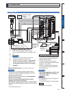
:KHQXVLQJDQH[WHUQDOG\QDPLFEUDNHEHVXUHWRXVHWKH
resistor.
Do not make short circuit.
Remarks
Remarks
U-phase
V-phase
:SKDVH
Terminals DB1, DB2, DB3 and DB4
7RFRQQHFWDQH[WHUQDOG\QDPLFEUDNH
UHVLVWRUGLVFRQQHFWWKHVKRUWLQJEDU
between DB3 and DB4.
&RQQHFWDPDJQHWLFFRQWDFWRUIRU
FRQWUROIRUWKHH[WHUQDOG\QDPLFEUDNH
EHWZHHQ/&DQG'%
3URYLGHDQH[WHUQDOSURWHFWLYHGHYLFH
(e.g. thermal fuse) between DB2 and
/&
7KHYROWDJHDSSOLHGDFURVV'%DQG
DB2 must be 300 VAC or below or
100 VDC or below.
Pin NC
'RQRWFRQQHFWDQ\WKLQJ
L3
L2
L1
/&
/&
9'&SRZHUVXSSO\
for brake
(to be supplied by
customer)
Thermal fuse
(one fuse for each resistor)
(to be supplied by customer)
Disconnect the
shorting bar
(between DB3
and DB4).
ワヤ
ワヤ
ワヤ
ロビヤ
ロヒヤ
ワヤ
ワヤ
ワヤ
ュャピ
ュャビ
ュャヒ
ュャフ
ヹヒ
ヹビ
ヹピ
ヹフ
ヹブ
ヹプ
ヤラモンヨユ
L1
L2
L3
B1
B2
NC
U
V
W
0DLQV
Residual
FXUUHQWGHYLFH
$X[LOLDU\FRQWDFW