


2-75
1
Before Using the Products
2
Preparation
3
Connection
4
Setup
5
Adjustment
6
When in Trouble
7
Supplement
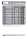
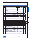
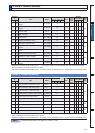
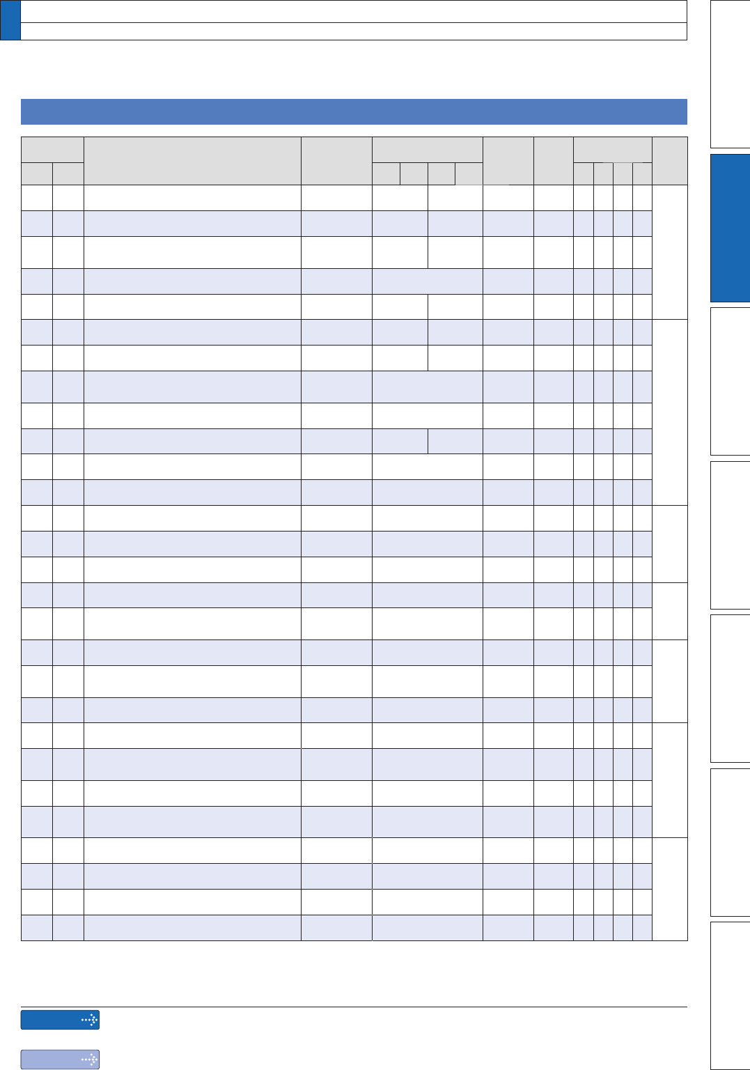
[Class 1] Gain adjustment
Parametr
No.
Title Range
Default
Unit
Turning
on of
power
supply
Related
Control Mode Detail
page
Class
No.
A,B
-frame
C
-frame
D,E,F
-frame
G,H
-frame
PSTF
1 00 1st gain of position loop 0 to 30000 480 320 0.1/s
*
4-13
1 01 1st gain of velocity loop 1 to 32767 270 180 0.1Hz
*
102
1st time constant of velocity loop
integration
1 to 10000 210 310 0.1ms
*
103VWÀOWHURIVSHHGGHWHFWLRQ 0 to 5 0 ï
104VWWLPHFRQVWDQWRIWRUTXHÀOWHU 0 to 2500 84 126 0.01ms
1 05 2nd gain of position loop 0 to 30000 570 380 0.1/s
*
4-14
1 06 2nd gain of velocity loop 1 to 32767 270 180 0.1Hz
*
107
2nd time constant of velocity loop
integration
1 to 10000 10000 0.1ms
*
108QGÀOWHURIVSHHGGHWHFWLRQ 0 to 5 0 ï
109QGWLPHFRQVWDQWRIWRUTXHÀOWHU 0 to 2500 84 126 0.01ms
*
1 10 Velocity feed forward gain 0 to 1000 300 0.10%
*
1119HORFLW\IHHGIRUZDUGÀOWHU 0 to 6400 50 0.01ms
*
1 12 Torque feed forward gain 0 to 1000 0 0.10%
*
4-15
1137RUTXHIHHGIRUZDUGÀOWHU 0 to 6400 0 0.01ms
*
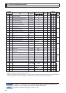
1 14 2nd gain setup 0 to 1 1 ï
1 15 Mode of position control switching 0 to 10 0 ï
4-16
116
Delay time of position control
switching
0 to 10000 50 0.1ms
*
1 17 Level of position control switching 0 to 20000 50 ï
4-17
118
Hysteresis at position control
switching
0 to 20000 33 ï
1 19 Position gain switching time 0 to 10000 33 0.1ms
*
1 20 Mode of velocity control switching 0 to 5 0 ï
4-18
121
Delay time of velocity control
switching
0 to 10000 0 0.1ms
*
1 22 Level of velocity control switching 0 to 20000 0 ï
123
Hysteresis at velocity control
switching
0 to 20000 0 ï
1 24 Mode of torque control switching 0 to 3 0 ï
4-19
1 25 Delay time of torque control switching 0 to 10000 0 0.1ms
*
1 26 Level of torque control switching 0 to 20000 0 ï
1 27 Hysteresis at torque control switching 0 to 20000 0 ï
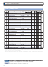
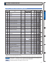
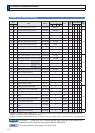
'HÀQLWLRQRIV\PEROVXQGHU´3RZHU2II2QµLIDFKDQJHLVPDGHLWZLOOEHUHÁHFWHGXSRQWKHSDUDPHWHUZKHQWKH
power to the driver is turned off and then on again.
*
'HÀQLWLRQRIV\PEROVXQGHU´5HODWHGPRGHµ3SRVLWLRQFRQWURO6YHORFLW\FRQWURO7WRUTXHFRQWURO)IXOOFORVHGFRQWURO
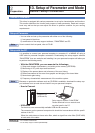
13.
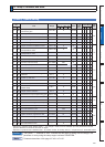
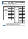
Setup of Parameter and Mode
List of Parameters
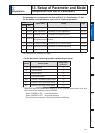
Caution
Note
The symbol “
*
” attached to “Unit”. indicates that the digits of setting unit will change if the
parameter is set by using the setup support software PANATERM.
Parameter describes of this page is P.4-13 to P.4-19.