3-51
1
Before Using the Products
2
Preparation
3
Connection
4
Setup
5
Adjustment
6
When in Trouble
7
Supplement
5. IF Monitor Settings
How to Assign Various I/O Functions to the I/F
Caution
Note
'RQRWVHWXSWRDYDOXHRWKHUWKDQWKDWVSHFLÀHGLQWKHWDEOH
'RQRWDVVLJQVSHFLILFIXQFWLRQWRRUPRUHVLJQDOV'XSOLFDWHGDVVLJQPHQWZLOOFDXVH
(UU,)LQSXWPXOWLSOHDVVLJQPHQWHUURURU(UU,)LQSXWPXOWLSOHDVVLJQPHQWHUURU
*
6HUYRRQLQSXWVLJQDO65921PXVWEHXVHGWRHQDEOHVHUYRRQ
*
:KHQXVLQJFRQWUROPRGHVZLWFKLQJLQSXW&02'(VHWWKHVLJQDOWRDOOFRQWUROPRGHV
,IWKHVLJQDOLVVHWWRRQO\RUFRQWUROPRGHV(UU,)LQSXWIXQFWLRQQXPEHUHUURU
RU(UU,)LQSXWIXQFWLRQQXPEHUHUURUZLOOEHJHQHUDWHG
7KHFRQWUROLQSXWSLQVHWWRLQYDOLGVWDWHGRHVQRWDIIHFWDQ\RSHUDWLRQ
)XQFWLRQVHUYRRQLQSXWDODUPFOHDUHWFWREHXVHGLQPXOWLSOHFRQWUROPRGHV
PXVWEHDVVLJQHGWRWKHVDPHSLQZLWKFRUUHFWORJLFDODUUDQJHPHQW,QFRUUHFWVHWWLQJ
ZLOOFDXVH(UU,)LQSXWPXOWLSOHDVVLJQPHQWHUURURU(UU,)LQSXWPXOWLSOH
DVVLJQPHQWHUURU
*
'HYLDWLRQFRXQWHUFOHDULQSXW&/FDQEHDVVLJQHGRQO\WR6,LQSXW:URQJDVVLJQPHQW
ZLOOFDXVH(UU&RXQWHUFOHDUDVVLJQPHQWHUURU
*
&RPPDQGSXOVHLQKLELWLQSXW,1+FDQEHDVVLJQHGRQO\WR6,LQSXW:URQJ
DVVLJQPHQWZLOOFDXVH(UU&RPPDQGSXOVHLQSXWLQKLELWLQSXW
,QSXWFLUFXLWUHIHUWR3DQGIXQFWLRQUHIHUWR3WR3
5HODWHGSDJH
33
61
X7
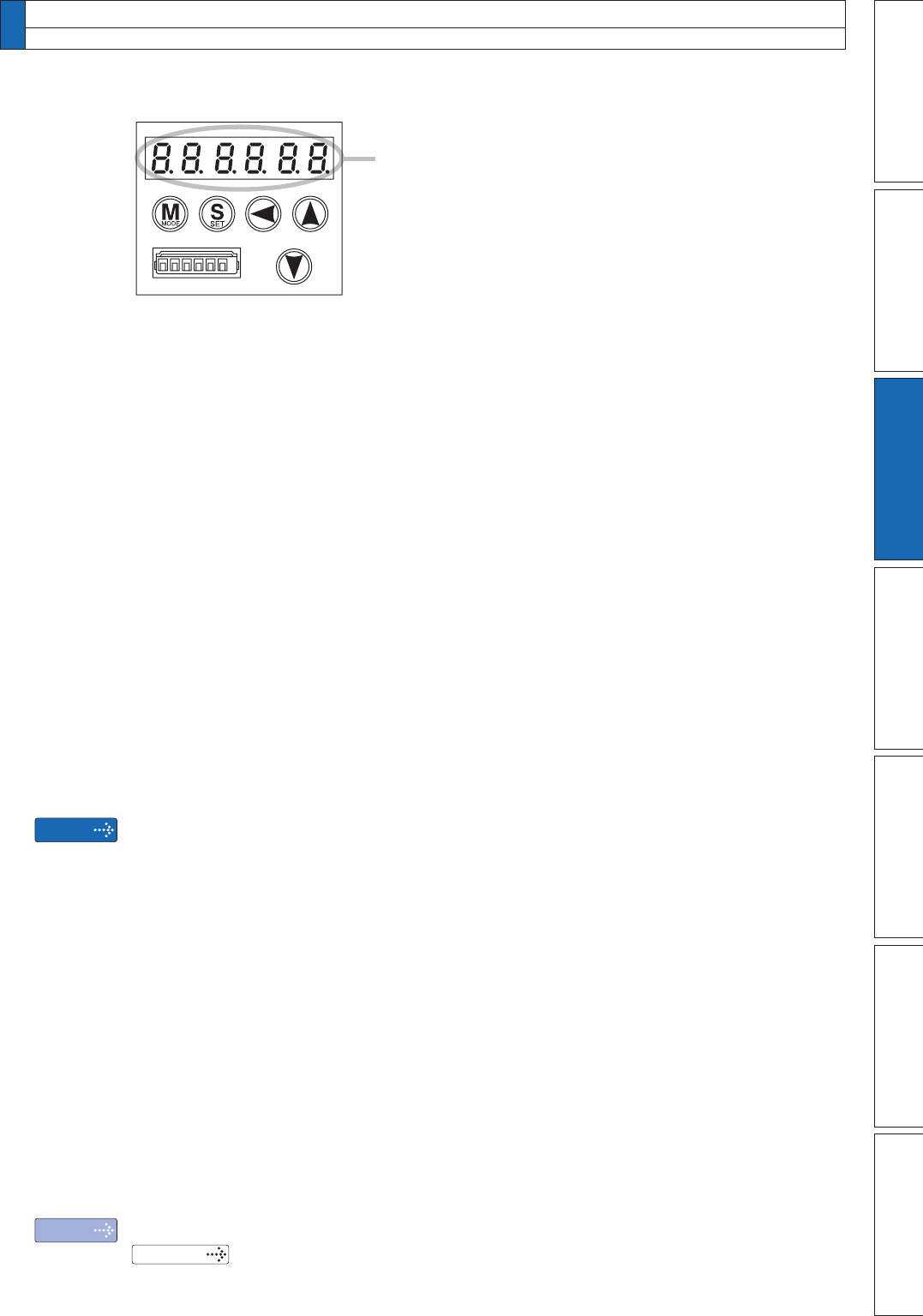
The front panel display is in decimal (six digits).
For setting functions and parameters, hexadecimal and
decimal numbers should be used respectively.
The expression of “00
h” indicates that the number
is hexadecimal.
The SI1 input (connector X4, pin No. 8) means that the negative direction over-travel
inhibition input is set to b-contact as a factory default.
For using the device in the position or full-closed control mode, the negative direction
over-travel inhibition input is set to b-contact by setting “8” and “2” in the seventh and eighth
digits from the left respectively. The settings in the first to sixth digits from the left do not
matter.
For the hexadecimal value “00000082h” or simply “82h”, enter “130” (decimal) to the
parameter Pr4.00.
To make multiple settings, enter the function number in the first eight digits from the left and
then enter a parameter in a decimal number after converting it from a hexadecimal number.
An example of this is shown in example 1 (the case on the left side).
Similarly, the SI3 input (connector X4, pin No. 26) has a function of damping control switching
input 1 as a default when used in the position control mode.
Also, if the speed control is used, it is set to the function of speed zero clamp input.
Therefore, in order to set it to the damping control switching input in the position control
mode, enter the value of “10” (decimal) in the parameter Pr4.02 meaning the hexadecimal
number “0Ah”, or “Ah”.
To change the speed zero clamp of pin No. 26 from b-contact to a-contact in the speed
control mode, enter the decimal number of “4352” in the parameter Pr4.02 meaning the
hexadecimal number of “00001100h”, or “1100h”.


