


2-85
1
Before Using the Products
2
Preparation
3
Connection
4
Setup
5
Adjustment
6
When in Trouble
7
Supplement
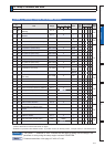
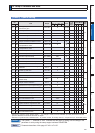
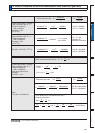
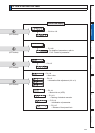
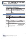
Electronic gear ratio
=
10
0.0005×2
17
×1
10×10
4
5×2
17
=
100000
655360
= 0.32768
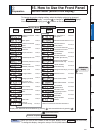
20
0.00005×2
17
×1
20
0.00005×2
20
×1
= =
20×10
5
5×2
20
2000000
5242880
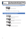
D < 1, hence
use 120-bit.
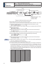
D =
L
уM×E×R
Electronic gear ratio
Travel distance per command pulse (mm)
(Position resolution)
D =
F × 60
N × E
“D = 1” is the
condition for
minimum resolution.
Pr0.09 = 655360
Pr0.10 = 100000
Pr0.09 = 5242880
Pr0.10 = 2000000
Pr0.09 = 262144000
Pr0.10 = 30000000
D =
Pr0.10
Pr0.09
Motor rotational speed (r/min),
N = F × × 60
E
D
= 50 × 60 × = 750
2
2
1
500000 × × ×60
10000
1×2
15
уM = × × L
E
D
2
17
1
1
1
R
1
× × × 20 =
3750
2
15
D = = =
500000×60
2000×2
17
30000000
2000×2
17
30000000
262144000
2
2
20
× =
3750
1
= 0.00133mm
3750 × 4
20
2
17
1
Lead of ball screw, L =10mm
Gear reduction ratio, R = 1
Position resolution,
у0 PP
Encoder, 17-bit
(E= 2
17
P/r)
Lead of ball screw, L =20mm
Gear reduction ratio, R = 1
Position resolution,
у0 PP
Encoder, 17-bit
(E= 2
17
P/r)
Lead of ball screw, L =20mm
Gear reduction ratio, R = 1
Position resolution,
у0 PP
Line driver pulse input,
500kpps
Encoder, 17-bit
Ditto
To make it to 2000r/min.
Encoder : 20-bit (E = 2
20
P/r)
D =
Pr0.10
Pr0.09
Related page
3´'HWDLOVRI3DUDPHWHUµ
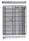
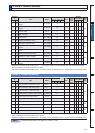
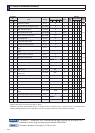
14. Setup of command division and multiplication ratio (electronic gear ratio)
Relation between Electronic Gear and Position Resolution or Traveling Speed