


1-9
1
Before Using the Products
2
Preparation
3
Connection
4
Setup
5
Adjustment
6
When in Trouble
7
Supplement
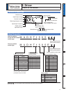
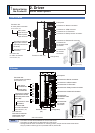
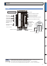
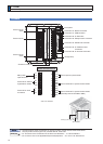
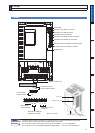
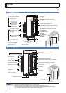
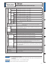
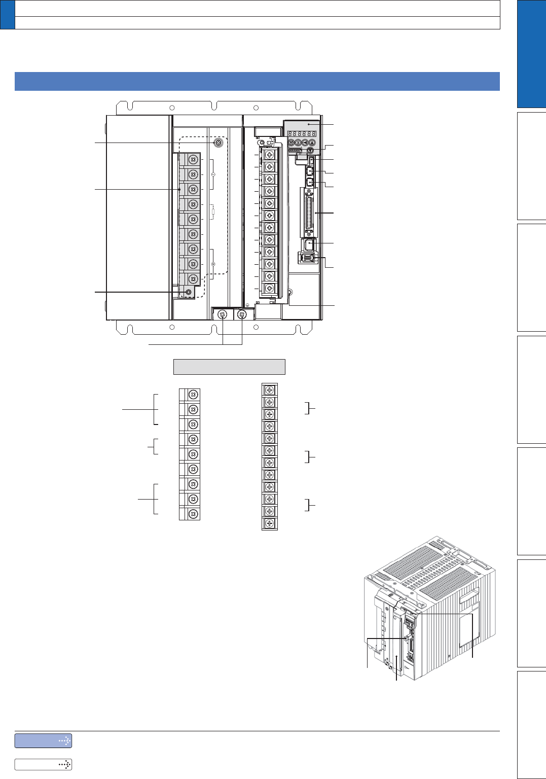
2. Driver
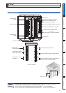
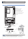
Parts Description
G-frame (400 V)
Terminal cover
LED cover
Safety by-pass prug
NC*
NC*
NC*
NC*
NC*
NC*
Control terminal for dynamic brake resister
Control terminal for dynamic brake resister
(Normally short-circuit DB3 to DB4.)
Details of terminal block
* NC is no connect.
NC*
24V
0V
DB1
DB2
DB3
DB4
L1
L2
L3
B1
B2
U
V
W
ワヤ
ワヤ
ワヤ
パヷ
ビフヷ
ワヤ
ワヤ
ワヤ
ュャピ
ュャビ
ュャヒ
ュャフ
ヹヒ
ヹビ
ヹピ
ヹフ
ヹブ
ヹプ
ヤラモンヨユ
フパパヷ
Control power input terminals
Screws for earth (x2)
Charge lamp
Connector X6: for encoder connection
Connector X4: Parallel I/O connector
Connector X3: Safety function connector
Connector X2: for Serial bus
Connector X1: USB connector
Connector X5: for feedback scale
connection
Connector X7: Monitor connector
Front panel
Main power
input terminals
Terminals for motor
connection
Terminals for external
regenerative resistor
L1
L2
L3
B1
B2
NC
U
V
W
Terminal cover
screw
Terminal cover
screw
Terminal cover
Note
Related page
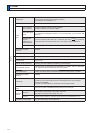
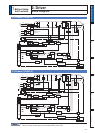
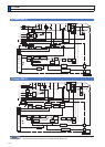
7KHÀJXUHDERYHVKRZVFRQQHFWLRQVRQYHORFLW\SRVLWLRQWRUTXHDQGIXOOFORVHGPRGHGULYHU
Only for position control type is not provided with X2, X3 and X5.
3´&KHFNRIWKH&RPELQDWLRQRIWKH'ULYHUDQGWKH0RWRUµ3´,QVWDOODWLRQµ
3´'ULYHUDQG/LVWRI$SSOLFDEOH3HULSKHUDO(TXLSPHQWVµ3WR´'LPHQVLRQVµ