


2-94
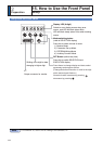
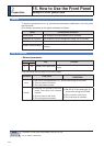
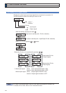
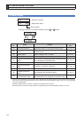
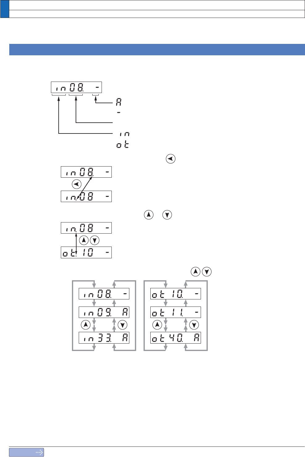
(5) Display of I/O Signal Status
Displays the control input and output signal to be connected to connector X4.
Use this function to check if the wiring is correct or not.
.....Input signal
.....Output signal
Pin No.
.....Active
*1
.....Inactive
*1
*1 When input signal Active : Input signal photocoupler is ON.
Inactive : Input signal photocoupler is OFF.
When output signal Active : Output signal transistor is ON.
Inactive : Output signal transistor is OFF.
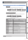
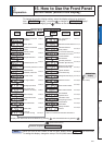
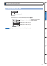
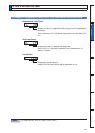
6HOHFWWKH3LQ1RWREHPRQLWRUHGE\SUHVVLQJ
6KLIWWKHIODVKLQJGHFLPDOSRLQWZLWK
6HOHFW,QRU2XWE\SUHVVLQJRUEXWWRQ
5LJKWVLGHRIGHFLPDOSRLQW3LQ1RVHOHFWLRQ
/HIWVLGHRIGHFLPDOSRLQW,QSXW2XWSXW3LQ1RVHOHFWLRQ
/RZHVWSODFH3LQ1R
RIRXWSXWVLJQDO
(Highest place Pin No.
RILQSXWVLJQDO
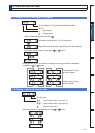
15. How to Use the Front Panel
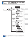
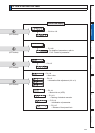
Monitor Mode (EXECUTION display)
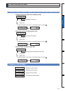
Note
For detail of input/output signal, refer to P.3-30 “Inputs and outputs on connector X4”
For detail of Error Code, refer to P.6-2 “Protective Function”.