


3-19
1
Before Using the Products
2
Preparation
3
Connection
4
Setup
5
Adjustment
6
When in Trouble
7
Supplement
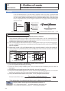
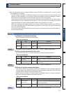
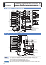
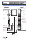
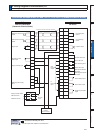
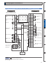
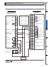
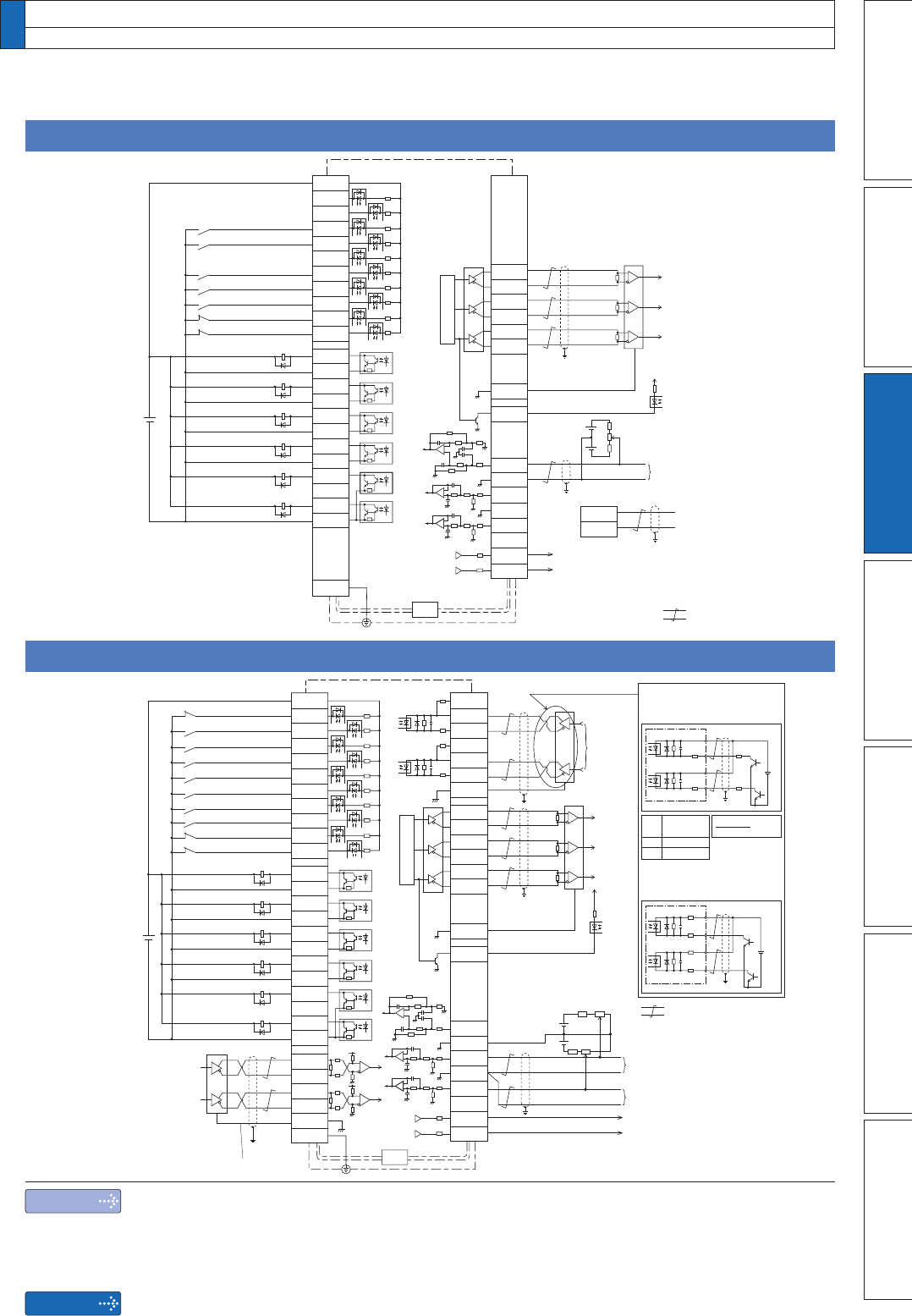
Wiring Example of Torque Control Mode
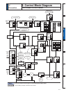
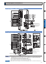
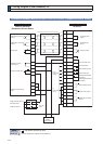
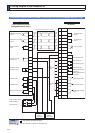
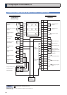
Wiring Example of Full-closed Control Mode
2.2kї
2.2kї
2.2kї
2.2kї
14
15
16
17
43
18
42
In case of open collector I/F
7
COM+
PULS2
SIGN1
SIGN2
GND
OA+
OA
-
OB+
OB
-
OZ+
OZ
-
GND
CZ
SPR/TRQR/SPL
GND
P-ATL/TRQR
GND
N-ATL
SP
IM
4
3
1
2
5
6
13
21
22
48
24
25
19
49
23
1kї
1kї
PULS1
OPC2
OPC1
INH
CL
SRV-ON
GAIN
DIV1
VS-SEL1
C-MODE
A-CLR
POT
NOT
S-RDY
+
S-RDY
-
ALM+
INP+
BRKOFF
+
BRKOFF
-
TLC
VDC
12 to 24V
ZSP
COM
-
SIGNH1
SIGNH2
PULSH1
PULSH2
GND
FG
INP
-
ALM
-
33
30
29
27
28
32
31
9
8
35
34
37
36
39
38
11
10
40
12
41
44
45
13
50
26
Z-phase output
(open collector)
3
PULS1
4
PULS2
X4
46
47
14kї
10kї
20kї20kї
14kї
10kї
20kї20kї
47kї
47kї47kї
47kї
20kї
20kї
+
–
+
–
–
20kї
2kї
2kї
20kї
120ї
20kї
2kї
2kї
20kї
120ї
220ї
VDC
R
5
SIGN1
6
SIGN2
220ї
R
1
OPC1
4
PULS2
220ї
24VDC
2
OPC1
6
SIGN2
220ї
2.2kї
2.2kї
(1) When you use the external
resistor with 12V and 24V
power supply
(2) When you do not use the
external resistor with 24V
power supply
Positive direction torque limit input
(0 to +10V)
Negative direction
torque limit input
(
-
10 to +10V)
Velocity monitor output
Torque monitor output
Command
pulse
input A
(Use with
500 kpps or less.)
Divider
A-phase
output
B-phase
output
Z-phase
output
Command pulse input B
(Use with 4Mpps or less.)
Be sure to connect.
V
DC
12V
24V
Specifications
of R
1kї1/2W
2kї1/2W
V
DC
-
1.5
R
+
220
=10mA
.
.
Servo-ON input
Gain switching input
Electronic gear
switching input 1
Control mode
switching input
Damping control
switching input 1
Alarm clear input
Positive direction
over-travel inhibition input
Negative direction
over-travel inhibition input
Servo-Ready output
Servo-Alarm output
Positioning complete output
External brake release output
Torque in-limit output
Zero speed detection output
Deviation counter
clear input
Command pulse
inhibition input
( : Twisted pair)
4.7kї
220ї
2.2kї
2.2kї
220ї
2.2kї
2.2kї
7
COM+
OA+
OA
-
OB+
OB
-
OZ+
OZ
-
GND
CZ
SPR/TRQR/SPL
GND
P-ATL/TRQR
GND
N-ATL
SP
IM
21
22
48
24
25
19
14
15
16
17
43
18
42
49
23
14kї
10kї
20kї20kї
14kї
10kї
20kї20kї
47kї
47kї47kї
47kї
20kї
20kї
1kї
1kї
INH
CL
SRV-ON
GAIN
DIV1
ZEROSPD
C-MODE
A-CLR
POT
NOT
S-RDY+
S-RDY
-
ALM+
AT-SPEED
+
BRKOFF
+
BRKOFF
-
TLC
VDC
12 to 24V
ZSP
COM
-
FG
AT-SPEED
-
ALM
-
33
30
29
27
28
26
32
31
9
8
35
34
37
36
39
38
11
10
40
12
41
50
Z-phase output (open collector)
X4
Divider
A-phase
output
B-phase
output
Z-phase
output
Torque command input or
velocity limit input (0 to ±10V)
Velocity monitor output
Torque monitor output
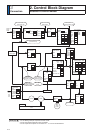
Wiring example when control mode Pr0.01=5 or Pr3.17=1
CCWTL/TRQR
GND
16
17
Negative direction torque
limit input
(0 to ±10V)
Select with Pr3.17.
+
–
+
–
+
–
Servo-ON input
Gain switching input
Alarm clear input
Servo-Ready output
Servo-Alarm output
At-speed output
External brake release output
Torque in-limit output
Zero speed detection output
Speed zero clamp
input
Control mode
switching input
Positive direction
over-travel inhibition input
Negative direction
over-travel inhibition input
( : Twisted pair)
4.7kї
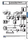
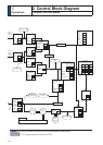
3. Wiring Diagram to the connector, X4
Example of control mode specific wiring
Note
Caution
7KHIXQFWLRQVRIWKHIROORZLQJSLQFDQEHFKDQJHGXVLQJSDUDPHWHUV5HIHUWR3
,QSXW7RUTXH2XWSXW
,QSXW)XOOFORVHG2XWSXW
3LQVLQWKHÀJXUHDERYHUHSUHVHQWGHIDXOWSDUDPHWHUYDOXHV
2QO\IRUSRVLWLRQFRQWUROW\SHLVQRWSURYLGHGZLWKDQDORJLQSXW
2QO\IRUSRVLWLRQFRQWUROW\SHLVQRWSURYLGHGZLWKFRQQHFWRU;
:LWKSRVLWLRQFRQWURORQO\W\SHGRQRWFRQQHFWDQDORJLQSXWRQSLQVDQGWR6*RISLQ