


6-21
1
Before Using the Products
2
Preparation
3
Connection
4
Setup
5
Adjustment
6
When in Trouble
7
Supplement
6
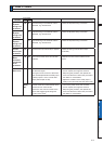
3. Troubleshooting
When in Trouble
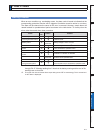
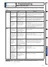
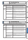
Motor Does Not Run
:KHQWKHPRWRUGRHVQRWUXQUHIHUWR3'LVSOD\RI)DFWRURI1R0RWRU5XQQLQJRI3UHSDUDWLRQ
as well.
&ODVVLÀFDWLRQ
Causes Measures
Parameter
Setup of the
control mode is
not correct
Check that the present
control mode is correct
with monitor mode of the
front panel.
6HWXS3UDJDLQ
2) Check that the input to control mode switching
&02'(RIWKH&QQHFWRU;LVFRUUHFWZKHQ
3ULVVHWWRWR
Selection of
torque limit is not
correct
Check that the external
analog input (N-ATL/
P-ATL) is not used for the
torque limit.
6HWXS3UWRDQGDSSO\>9@WR1$7/DQG
>9@WR3$7/ZKHQ\RXXVHWKHH[WHUQDOLQSXW
6HWXS3UWRDQGVHWXSWKHPD[YDOXHWR
3UZKHQ\RXXVHWKHSDUDPHWHUYDOXH
Setup of
electronic gear
is not correct.
(Position/Full-
closed)
Check that the motor
moves by expected
revolution against the
command pulses.
&KHFNWKHVHWXSVRI3U3UDQG3UWR
3UDJDLQ
2) Connect the electronic gear switching input (DIV) of
&RQQHFWRU;WR&20²RULQYDOLGDWHWKHGLYLVLRQ
multiplication switching by setting up the same
YDOXHWR3UDQG3U
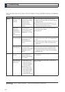
Wiring
Servo-ON input
of Connector
;65921LV
open.
In the front panel monitor
mode, is the Pin No.
corresponding to SRV-
ON in “ - ” state?
Check and make a wiring so as to connect the SRV-
21LQSXWWR&20²
Positive/negative
direction over-
travel inhibit input
RI&RQQHFWRU;
(NOT/POT) is
open.
In the front panel monitor
mode, is the Pin No.
corresponding to NOT/
POT in “ A ” state?
1) Check and make a wiring so as to connect both
127327LQSXWVWR&20²
6HWXS3UWRLQYDOLGDQGUHVHWWKHSRZHU
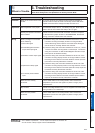
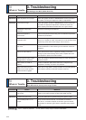
Command pulse
input setup
is incorrect.
(Position/Full-
closed)
Check that the input
pulse counts and
variation of command
pulse sum does not slips,
with monitor mode of the
front panel.
1) Check that the command pulses are entered
FRUUHFWO\WRWKHGLUHFWLRQVHOHFWHGZLWK3U
2) Check that the command pulses are entered
FRUUHFWO\LQWKHIRUPDWVHOHFWHGZLWK3U
Command
pulse input
LQKLELWLRQ,1+RI
&RQQHFWRU;LV
open. (Position/
Full-closed)
In the front panel monitor
mode, is the Pin No.
FRUUHVSRQGLQJWR,1+LQ
“ A ” state?
&KHFNDQGPDNHDZLULQJVRDVWRFRQQHFWWKH,1+
LQSXWWR&20²
2) Set up Pr5.18 to 1 (invalid).
Counter clear
input (CL) of
&RQQHFWRU;
is connected to
&20²3RVLWLRQ
Full-closed)
In the front panel monitor
mode, is the Pin No.
corresponding to CL in
“ A ” state?
1) Check and make wiring so as to open the CL input
6HWXS3UWRLQYDOLG
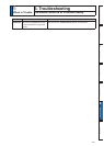
Related page
3´+RZWR8VHWKH)URQW3DQHOµ3´,QSXWVDQGRXWSXWVRQFRQQHFWRU;µ
3´'HWDLOVRISDUDPHWHUµ