7-97
1
Before Using the Products
2
Preparation
3
Connection
4
Setup
5
Adjustment
6
When in Trouble
7
Supplement
LINE LOAD
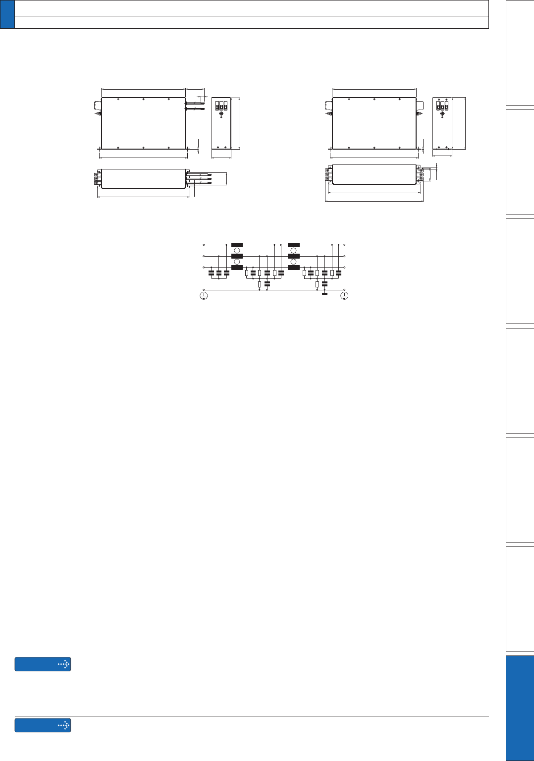
Circuit diagram
[FN258-42-07] [FN258-42-33]
E E
L3
L2
L1
L3'
L2'
L1'
314
300
329
1.5
70
500±10
45
6.5
12
185
350
70
314
329
45
6.5
300
185
1.5
[Unit: mm][Unit: mm]
7. Options
Noise Filter
Caution
Use options correctly after reading operation manuals of the options to better un-
derstand the precautions.
Take care not to apply excessive stress to each optional part.
Remarks
6HOHFWDQRLVHÀOWHURIFDSDFLW\WKDWH[FHHGVWKHFDSDFLW\RIWKHSRZHUVRXUFHDOVR
check for load condition).
)RUGHWDLOHGVSHFLÀFDWLRQRIWKHÀOWHUFRQWDFWWKHPDQXIDFWXUHU


