


3-25
1
Before Using the Products
2
Preparation
3
Connection
4
Setup
5
Adjustment
6
When in Trouble
7
Supplement
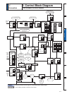
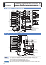
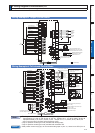
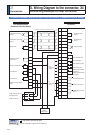
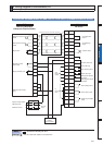
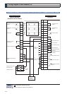
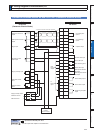
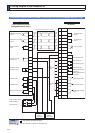
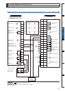
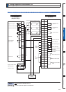
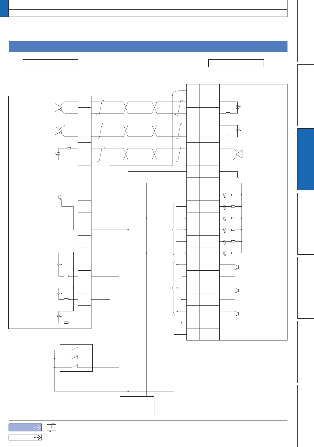
3. Wiring Diagram to the connector, X4
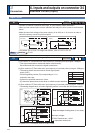
Connecting Example to Host Controller
Note
5HODWHGSDJH
UHSUHVHQWVWZLVWHGSDLUZLUH
3´,QSXWVDQGRXWSXWVRQFRQQHFWRU;µ
Connection between MINAS A5 and F3NC32-ON/F3NC34-ON (Yokogawa Electric Corp.)
A5-seriesF3NC32-ON/F3NC34-ON
(Yokogawa Electric Corp.)
from
PLC I/O
output
to
PLC I/O
input
GND
+ 24V
DC24V
Power supply
Command
pulse
input 2
Counter clear input
Servo-ON input
Servo-Ready output
Servo-Alarm
output
Positioning complete
output
Alarm clear input
Inhibit negative direction
travel input
Inhibit positive direction
travel input
Z-phase output
Command sign
input 2
Gain switching input
DriverPLC
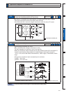
CCW limit sensor
Origin proximity sensor
CW limit sensor
Pulse output A
Pulse output B
Origin input
Deviation counter
reset output
Contact point
input COM
External power supply
24VDC input
External power supply
24VDC input (GND)
Negative direction
limit input
Positive direction
limit input
Encoder Z-phase
output +
Encoder Z-phase
output –
* Process of shield wire varies with equipment.