


Installing the Modules
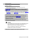
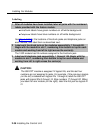
NOTE:
DIP switches 1, 2, 6 and 7
unprotected. DIP switches
mode is always protected.
DIP switches 1, 2, 6 and 7
determine whether the tie trunks are protected or
3, 4, 5, 8, 9, and 10 determine the mode. Simplex
Therefore the Protected/Unprotected settings for
have no effect.
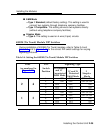
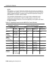
The successful implementation of a tie trunk format is dependent upon
matching the characteristics of both the PBX systems it connects. The
preferred signaling formats for a tie trunk originating in the system are shown
in Table 2–5 below.
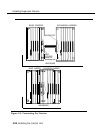
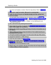
Table 2-5. Signaling Formats for the 400EM (Tie Trunk) Module
Installation Situation
Preferred Signaling Format
From System
System
Distant Location
Distant Signaling
Protected or
Signaling
Protected or
To
Location
Mode/Type
Unprotected Mode/Type
Unprotected
MERLIN II
Same site
Type 5 Simplex
N/A Type 5 Simplex
N/A
co-located
System
Same site
Type 5 Simplex
N/A Type 5 Simplex N/A
25/75/85 co-located
or DEFINITY
System
Inter-office Type 5 Simplex
N/A
Type 5 Simplex
N/A
25/75/85
or DEFINITY
Dimension PBX Same site
E&M Type 1 C
Unprotected
E&M Type 1 S
Unprotected
co-located (Compatible)
(Standard)
Dimension PBX Inter-office E&M Type 1C
Protected
E&M Type 1 S
Protected
(Compatible)
(Standard)
Other Systems
Same site
E&M Type 1 C
Unprotected
E&M Type 1S
Unprotected
co-located
(Compatible) (Standard)
Other Systems
Inter-office
E&M Type 1 C
Unprotected
E&M Type 1 S
Requires a
(Compatible)
(Standard)
protection unit
MERLIN
Same site
Type 5 Simplex
N/A
Type 5 Simplex
N/A
LEGEND co-located
or inter-office
2-36 Installing the Control Unit