


Checking System and Slot Status
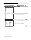
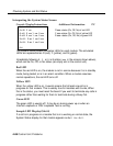
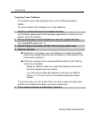
Interpreting the System Status Screen
Console Display/Instructions
Additional Information PC
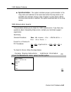
System Status:
Slot00: R aaa
R aaa =status (On, Off, No) of red LED
Slot01 R aaa Y aaa G aaa
Y aaa =status (On, Off, No) of yellow LED
Slot02 R aaa Y aaa G aaa
G aaa =status (On, Off, No) of green LED
Slot03: R aaa Y aaa G aaa
Slot04: R aaa Y aaa G aaa
Exit
The System Status screen simulates LEDs for each module. The simulated
LEDs are represented as R (red), Y (yellow), and G (green).
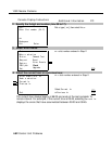
Immediately following
R, Y,
or
G
is its status
(aaa
in the screens shown above),
which can be On, Off, or No status (an empty slot in the control unit).
Red LED
When the red LED is on, the module is not in service because it is in standby
mode, being tested, or is in an alarm condition. When a module resumes
normal operations, the red LED turns off.
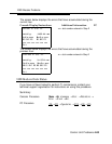
Yellow LED
When the yellow
progress on that
this is the status,
LED is on, it usually means that at least one call is in
module. This is usually true for modules with trunks, When
you must reset the board if you want to terminate any calls in
progress rather than waiting for them to terminate during a Busy-Out.
Green LED
The green LED is usually off. It may be on during power up or when an
Internal Loopback or CSU Loopback Test is running.
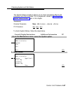
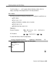
Sample LED Display (Slot 4)
If a call is in progress on a module that is in a working or normal state, the
System Status display for that module appears as
Roff Yon Goff.
4-88 Control Unit Problems