


Wiring
Wiring
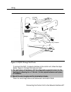
The local telephone company should have installed the network interface (the
central office trunks) already. Before you install the system, verify that the
network interface is the proper type and that it is within 25 ft. (7.6 m) of the
control unit. If the network interface is more than 25 ft. (7.6 m) from the control
unit, make sure you have an OPRE.
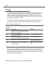
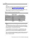
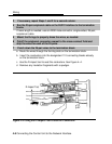
The adapter you need to connect the central office trunks to the control unit
depends on the type of network interface installed, as shown
in Table
4-1.
Table 4-1. Network Interfaces
Network
Interface
Description
Adapter
RJ11
Connects one outside ground-start (GS),
loop-start (LS), or Direct Inward Dial (DID)
trunk to one modular jack.
RJ14
Connects two outside trunks to one modular
2-line adapter (267C-type)
jack (GS, LS, or DID).
RJ21X
50-pin connector connects 25 110AB1 jack- 110AB1 jack-panel block
panel block to outside trunks (GS, LS or DID)
RJ2GX
50-pin connector for up to eight tie trunks
356A for eight or fewer tie
trunks; 259A for one tie trunk
RJ48C/X
Connects DS1 facilities to a four-pair jack
Z601A if modular cords are
(two active pairs).
used
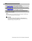
After installing the adapter, label each jack that connects a central office trunk
to the control unit with the trunk’s number. Use the list provided by the local
telephone company or System Form 2c, System Numbering: Line/Trunk Jacks
for outside trunks as a reference.
4-2 Connecting the Control Unit to the Network Interface