Video Conferencing Data Stations
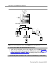
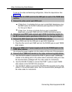
7 If it is not already connected, connect the CSU to the 100D module on the
control unit and to the 5ESS or 4ESS exchange switch,
See “lnstalling the Channel Service Unit” in Chapter 4.
8 When you are ready to power up the system, plug the power supplies,
CSU, video conferencing equipment, and control unit into the AC outlets.
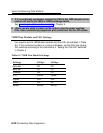
7500B Data Module and CSU Settings
You need to set the 7500B data modules and the CSU as indicated in Table
6-2. If the customer’s system is running at 56 kbps, set the CSU line-coding
DIP switches according to the instructions in “Setting the CSU DIP Switches”
in Chapter 4.
Table 6-2. 7500B Data Module Settings
Settings
56 Kbps
64 Kbps
Auto-dial
Off
Off
Busy out
Off
Off
Datarest
On
Off
DTR
Follow
Follow
Duplex
Full Full
Mode
Cs
Cs
Speed
56,000 64,000
6-20 Connecting Data Equipment


