


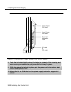
Installing the Processor
CAUTION:
Before touching leads, connectors, pins, and other components when
handling the circuit board, use a properly grounded wrist strap to
prevent damage from electrostatic discharge (ESD).
Installing the Processor in the Carrier
1
2
3
4
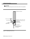
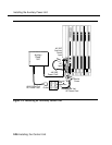
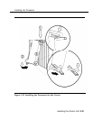
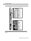
To install the processor in the carrier, follow the steps below, Refer to Figure
2-10.
Remove the protective cover from the gold-finger connector on the back
of the processor.
Lower the hook on top of the processor module onto the rod on top of
the carrier in Slot 0, the first slot next to the power supply.
Make sure that the connector on the module mates properly with the
connector on the carrier as you swing the processor down into place.
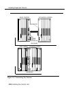
CAUTION:
To avoid damage, do not force the module. If the module does not insert
easily, press the bottom rear locking tab, remove the module, and
inspect the module and carrier for damage or obstruction. The bottom-
rear locking tab is shown in Figure 2–10. This tab is used on all
modules.
If there is no damage and no obstruction, reinsert the module.
A damaged carrier or module must be replaced.
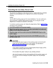
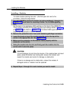
Push firmly until the processor snaps into place.
The processor should be securely attached to the carrier and locked in place
by the locking tab on the bottom rear of the processor.
2-30 Installing the Control Unit