


Checking System and Slot Status
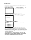
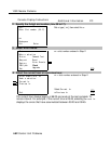
5
6
7
8
9
10
11
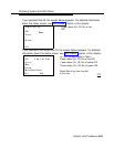
Remove the processor, the power supply, and all other modules from the
faulty carrier. (If you prefer to remove the cords first, make sure they are
labeled.)
Put the modules aside, in order, so that you can reinstall them later in the
replacement carrier.
Remove all modules from the carriers to the right of the faulty carrier.
Starting with the rightmost carrier, loosen the four screws that secure the
four corners of the carrier to the backboard.
Slide the carrier to the right until the connector disengages from the
carrier to the left.
Pull the carrier away from the wall so that the screws slip through the
large screw holes.
Repeat Steps 8-10 until the faulty carrier is removed.
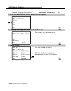
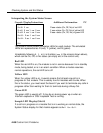
Replacing the Carrier
After removing the faulty carrier, use the steps below as a guideline for
installing a new carrier.
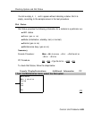
1 Install the replacement carrier(s). See Installation for instructions.
2 Replace the modules with all cords connected as they were before.
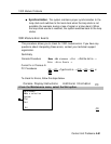
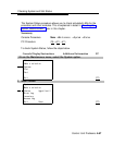
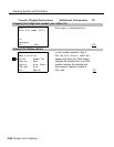
Checking System and Slot Status
In addition to checking error logs, the access log, and running module tests,
you can request System Status and Slot Status information for each module.
System Status
The power supply, processor, 400EM module, and 10OD module are the only
modules that have LEDs. The System Status screen displays simulated LEDs
for the processor and each of these modules but not for the power supply.
4-86 Control Unit Problems