


7500B Data-Only Stations
7500B Data-Only Stations
.
1
2
3
4
5
6
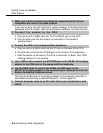
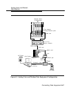
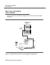
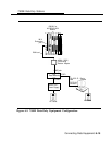
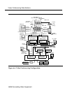
Figure 6-5 shows an equipment configuration for a 7500B data-only station.
To set up a 7500B data-only station, follow the steps below:
Use an EIA-232-D cable to connect the SERIAL port on the data terminal
to the 7500B data module.
For any data terminal that has both COM1 and C0M2 connectors, make sure
you use the one designated for data transmission. See the customer’s system
manager if you are not sure.
Make sure that the 7500B data module option settings for parity and
speed are compatible with the data terminal. (Speed is synchronized
automatically if the factory setting has not been changed.)
If you are not sure about the speed and parity of the data terminal, see the
customer’s system manager or the documentation packaged with the 75006
data module and the data terminal.
Plug the other end of the EIA-232-D cable into PORT 1 on the 7500B data
module.
Plug the WP90110-L7 power supply cord into the POWER receptacle on
the 7500B data module.
Use a 440A4 terminating resistor adapter to connect the 7500B data
module to the control unit.
a Use a D8W cord to connect the 440A4 terminating resistor adapter to the
LINE jack on the 7500B data module.
b Use a second D8W cord to connect the other end of the adapter to the
appropriate MLX extension jack. See Form 2b, System Numbering: Digital
Adjuncts for the appropriate module and extension jack.
Connect all power cords to an AC outlet not controlled by a wall switch.
6-14 Connecting Data Equipment