


Installing the Basic Carrier
Unit Loads for Key or Behind Switch Mode
In a Key or Behind Switch system with four or fewer modules, no calculation is
needed. The power supply (model 391A1) generally supports four modules of
any type.
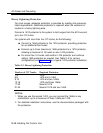
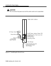
Auxiliary Power Units
The power supply provides 54 unit loads to each carrier. If the unit load
requirement for a carrier exceeds 54, an auxiliary power unit is needed to
allow that carrier to support up to an additional 27 unit loads.
CAUTION:
Running the system with more than 54 unit loads per carrier may not
appear to do harm. However, this can cause the system to malfunction,
creating “NO Trouble Found” situations, such as malfunctioning LEDs on
multiline telephones or power unit failure.
Any extension that is connected to the modules in the last two slots receives
power from the auxiliary power unit instead of from the power supply.
If an auxiliary power unit is required, refer to “Installing the Auxiliary Power
Unit,” later in this chapter, for instructions.
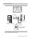
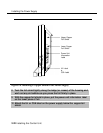
Installing the Basic Carrier
Continue with this procedure only if you have met all of the requirements
discussed earlier in this chapter.
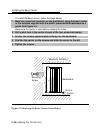
NOTE:
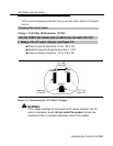
When you mount the basic carrier onto the backboard, leave 29 in. (73.66 cm)
of backboard to the right. This allows you to easily install and remove the
control unit cover, and also allows enough room for system expansion to the
right for the total length of up to three carriers.
Installing the Control Unit 2-17