Figures
7
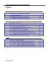
Initializing and Testing the System
7–1. Ground-Start Button
7-18
7–2. Installing the Control Unit Top Cover
7-21
7–3. Installing the Control Unit Front Cover
7-22
9
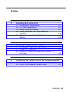
Upgrading the System
9–1. Removing the Control Unit Housing
9-2. Powering Down the System
9-3. Removing a Module from the Carrier
9–4. Replacing a Module in the Carrier
9–5. Removing the Processor Module Cover
9-6. Removing the Processor Module Circuit Board
9–7. Changing the Key Mode Switch Position to Closed
9-8. Installing the Control Unit Housing
9-3
9-5
9-7
9-9
9-11
9-12
9-13
9-17
A
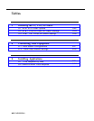
System Numbering Forms
A–1. Form 2a, System Numbering: Extension Jacks
A-2
A–2. Form 2b, System Numbering: Digital Adjuncts
A-4
A-2. Form 2c, System Numbering: Line/Trunk Jacks
A-5
A-4. Form 2d, System Numbering: Special Renumbers
A-6
xii Installation


