


Upgrading the Control Unit
a
b
c
d
e
f
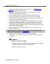
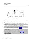
Remove the rightmost module from the control unit. See “Removing a
Module” in Chapter 2 for instructions.
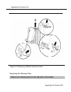
Using a flat-blade screwdriver, unscrew the upper-right corner of the
carrier only far enough to free the clip.
Pull the top-right corner of the carrier toward you while grasping the
housing clip and pushing it away from you (to free it from the carrier).
When the clip is free enough to clear the screw molding on the back of the
carrier, slide the clip out and discard it.
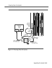
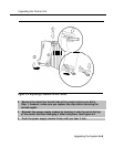
Compare the Control Unit Diagram with the existing control unit. If you are
installing an additional expansion carrier in this upgrade, do not replace
the clips on the right side until the last expansion carrier is installed. If no
more carriers are to be installed, replace the clip now, making sure the clip
is as far to the right as possible.
Secure the screw, and then repeat Steps b, c, and d for the lower right
corner of the carrier.
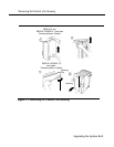
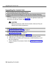
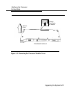
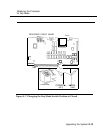
2 Remove the power supply module to access the housing clips on the
leftmost side of the carrier. See Figure 9-3.
a Press up on the tab at the bottom rear of the power supply.
b While the tab is unlocked, pull the power supply towards you, and then lift
it straight up.
WARNING:
Beware of hazardous voltages.
Whenever the carrier connections are exposed, use extreme caution;
do not touch them directly or with any type of tool.
Follow all procedures carefully.
9-8 Upgrading the System