


Chapter 4 Selecting the media bay modules for your system 95
Installation and Maintenance Guide
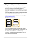
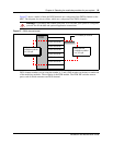
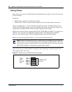
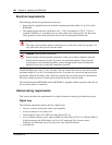
Figure 27 shows a model of how the DS30 channels are a subgroup of the DS256 channel on the
MSC. The diagram also shows offsets, which are a subgroup of the DS30 channels.
Figure 27 DS30 channel model
DS30 channel numbers are set using the number 4, 5, and 6 DIP switches on the back or underside
of the media bay modules. The exception is the FEM module. The FEM DIP switches turn on
ports, each of which consumes one DS30 channel.
Warning: If you change the channel split from 3/5 to 2/6 after your system is configured,
you will lose all the data and optional application connections.
DS256
on MSC
DS30 channel #2
DS30 channel #3
DS30 channel #4
DS30 channel #5
DS30 channel #6
DS30 channel #7
DS30 channels
available to modules
in a 2/6 split
Four offsets per channel
DS30 channels
available to modules
in a 3/5 split