


Chapter 10 Wiring the modules 157
Installation and Maintenance Guide
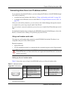
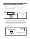
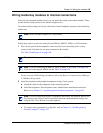
Connecting media bay modules to Service Providers
To connect DTM, CTM, CTM8, 4X16, or BRI media bay modules to the network, follow these
steps:
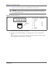
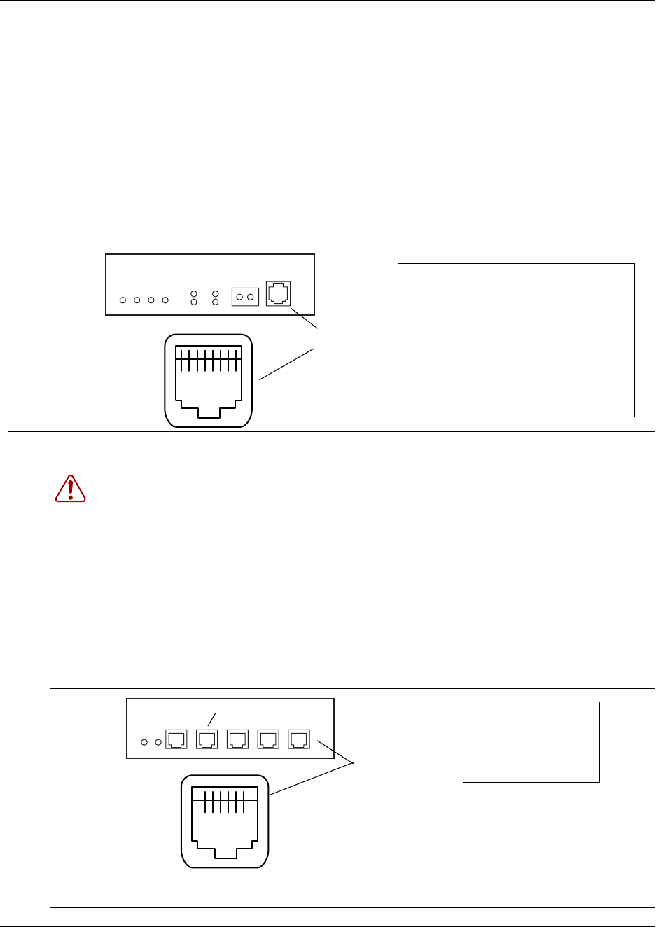
1 On the front of the module, locate the RJ48C socket (DTM), RJ45 sockets (BRI), or the
RJ11 sockets (CTM and 4X16 modules).
2 Wire one end of the cable to the telco demarcation blocks of the building.
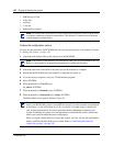
• Figure 53 shows the wiring pinouts for a DTM to connect to a service provider.
Figure 53 DTM RJ48C wiring array
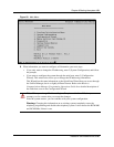
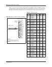
• Figure 54 shows the wiring pinout for a CTM, a CTM8, or the CTM jacks on a 4X16
module, to connect to the service provider.
All the modules have an auxiliary jack (the CTM8 has two). Do not attempt to plug digital
equipment into this jack.
Figure 54 CTM RJ11 wiring array
Warning: If you are using a service provider channel service unit (CSU), you must
disable the Business Communications Manager system internal CSU using Business
Communications Manager Unified Manager. For more information, refer to the Business
Communications Manager 2.5, Programming Operations Guide.
1 2 3 4 5 6 7 8
DTM connector
To network To plug
Receive from
network
1- Rring
2 - Rtip
3 - Rshield
Transmit to network
4-Tring
5-Ttip
6-Tshield
RJ48C jack
6 5 4 3 2 1
CTM
connector
RJ11 sockets
Auxiliary jack
Pin #/connection
3- Ring
4 - Tip
The CTM 8 has eight RJ11 jacks, including two
auxiliary jacks.
The 4X16 media bay module has four RJ11 jacks.