


Chapter 2 Telephony hardware 75
Installation and Maintenance Guide
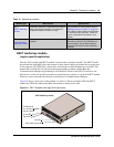
Caller ID Trunk media bay module
(North American systems only)
The CTM and CTM 8 have the same functions.
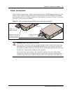
• The Caller ID Trunk media bay module (CTM) connects a maximum of four analog calling
line ID (CLID) interfaces to the Business Communications Manager system via four RJ11
jacks on the module face. These jacks are labeled: Line 1, Auxiliary, Line 2, Line 3, and Line
4. The auxiliary jack connects to Line 1.
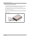
• The CTM8 provides eight analog CLID interfaces to the Business Communications Manager
via eight RJ11 jacks on the module face. Each jacks also supports disconnect supervision.
There are two auxiliary jacks on this module which connect to Line 1 and Line 5. Note that the
top line of jacks is numbered in reverse order.
The auxiliary ports permit you to connect a V.90 modem, FAX machine, or single-line analog
telephone. When the auxiliary device is active, the Business Communications Manager system
blocks the associated line. Conversely, when the line is active, the auxiliary port line is blocked.
When you connect a single line analog telephone to the auxiliary port, you can use it as an
emergency telephone because this line remains active if a power outage occurs.
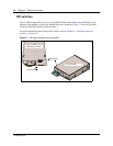
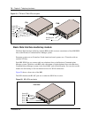
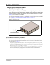
Figure 19 provides a view of the front of the CTM and CTM8.
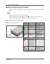
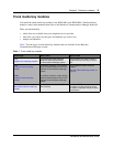
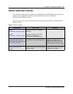
Transmit Alarm On indicates the DTM cannot transmit. The DTM sends an Alarm indication signal
(AIS) to the terminating switch. This half-duplex link does not work.
Transmit Error On indicates the DTM is sending a remote alarm indication (RAI) carrier failure
alarm (CFA) to the terminating switch. If the Transmit Alarm is not on, this error
indicates a far-end or cable problem.
All LEDS flashing All LEDs flashing continuously indicates that the DTM is initializing.
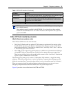
TIP: You can install a maximum of three DTMs in the BCM1000 system, depending on
the available channels.
These modules must be installed in the BCM1000. If you already have three modules
installed in the BCM1000, move one of those modules to the expansion unit to provide
space for the DTM
Table 8 DTM LED functions (Continued)
LED label Function