


Chapter 17 Replacing the hard disk 235
Installation and Maintenance Guide
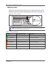
In the mirrored disk configuration, the RAID controller board automatically writes the same data
from the primary hard disk to the secondary/mirrored disk. Once this is complete, the board
ensures that the disks remain identical. With this configuration, if one disk fails, the second disk
has an exact copy of the current information and the system continues to function. This minimizes
recovery time after disk failure.
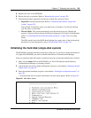
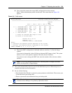
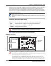
Connecting RAID board ribbon cables
The RAID board has three labelled ribbon connectors, which connect to the following:
• Host connects to the IDE 1 connector on the control board (motherboard)
• Mirrored connects to the secondary (mirroring) hard disk
• Primary connects to the primary hard disk
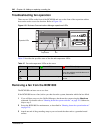
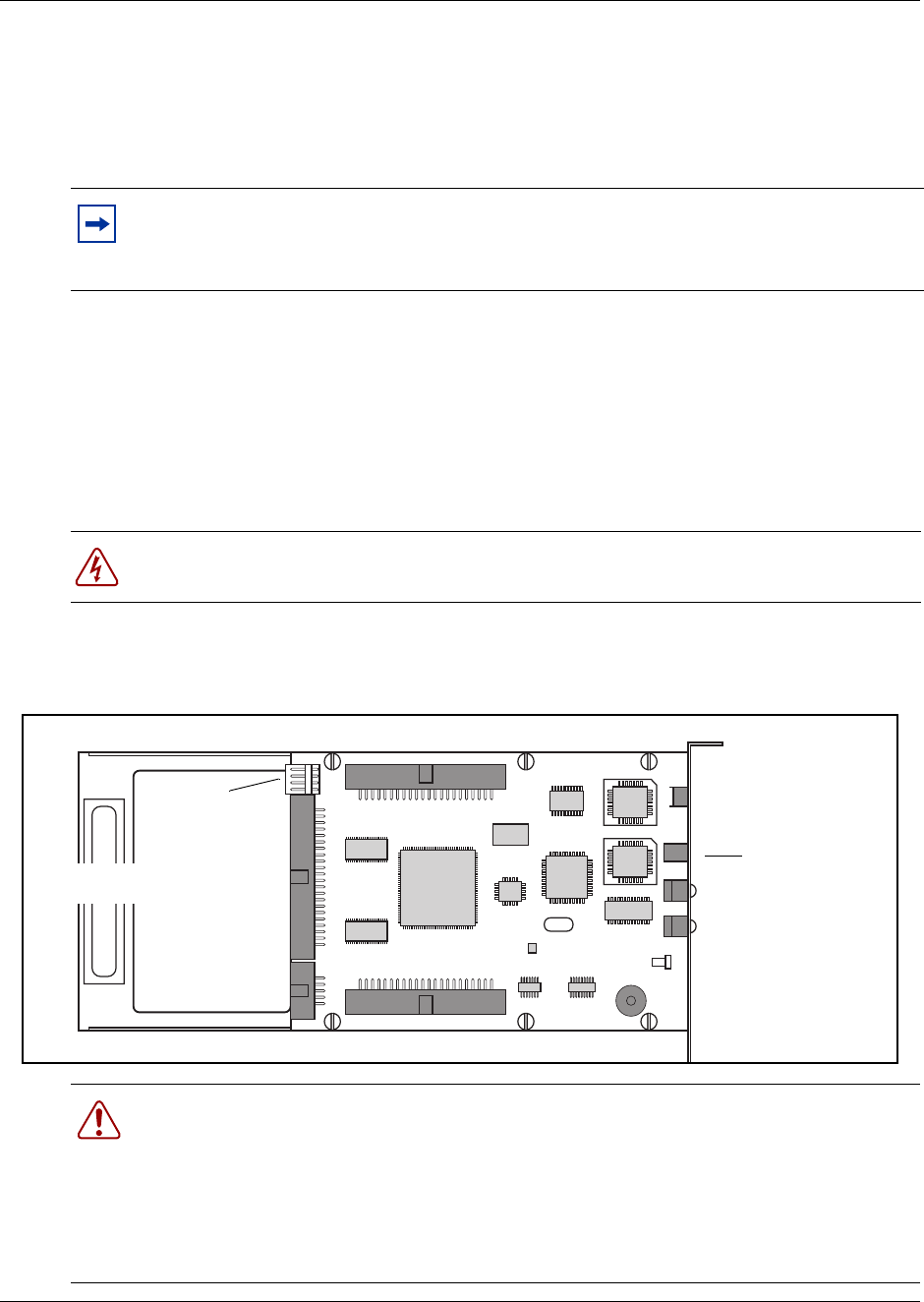
Figure 105 shows the location of these connectors on the RAID board.
Figure 105 RAID Board
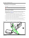
Note: Backup and restore data
Remember to continue to do data backups that get stored off-site, as part of your recovery
strategy.
Danger: The RAID board connectors are NOT hot-swappable. Ensure that the system is
powered down before you attempt to connect or disconnect any of the cables.
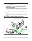
Warning: Reconnecting Mirrored and Primary cables
After maintenance, the Mirrored and Primary cables must always be attached to the same
hard disk positions from which they were removed.
This means that if the Primary disk fails, the Primary cable gets connected to the new
blank disk. Mirroring then occurs from the Mirrored disk to the blank Primary disk. Once
mirroring has completed, the Mirroring disk hands over control to the new Primary disk.
Mirrored disk cable connector
Face of board
with LEDs
Primary disk cable connector
Host (Motherboard cable
connector)
Power connector