


BCM1000 version 3.0 addendum 19
Upgrading from a standard system
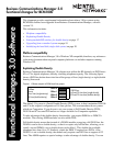
When you upgrade your BCM1000 from a single power supply and fan to a redundant system, you need to remove
the jumper from the connectors on the System Status Monitor board to allow the cables from the redundant
equipment to be connected.
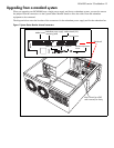
The diagram below notes the location of the connectors for the redundant power supply and for the redundant fan.
Figure 1 System Status Monitor internal connectors
SSM board
J7
J6
Mother board
Redundant power supply
monitoring cable
Mother board (J10)
Board power
Redundant/primary fans
CPU fan
Remote temperature
sensor
Note: Chassis has all PCI
cards removed, for clarity