


70 Chapter 2 Telephony hardware
P0993298 02
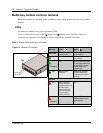
Media bay module common features
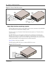
Media bay modules are designed within a common casing, which includes the following common
features:
LEDs
All media bay modules have power and status LEDS.
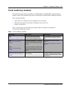
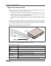
Figure 15 shows the location of the (Power) and (Status) on a CTM. These LEDs are
located in the same place on all modules. Table 6 describes the common LED states.
Table 6 Module Power and Status LED states
Figure 15 Module LED locations
LED state
Power
Status
Green LED
Indicates state of
module power
Indicates condition of
module status
On Normal operation All monitored services
are working.
Flashing
N/A KSU startup (slow flash)
or (fast flash) there may
be a problem with the
DS256 cable or the
DS256 clock
Off Module is not
powered
Module not powered
(reseat module) OR
hardware fault (replace
module)
*Red LED
On Power converter
failure. Power to
telephones may not
be within spec.
(check base unit
LEDs for possible
power issue or
replace module)
N/A
Flashing
N/A Loss of DS256 clock, or
DS256 cable may be
disconnected.
* Not all modules have red LEDs
CTM
Power LED
Status LED