


Chapter 9 Starting the system 145
Installation and Maintenance Guide
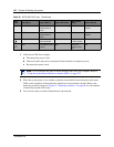
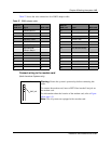
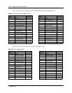
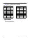
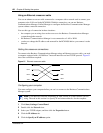
Table 27 shows the wire connections for a DB25 adapter cable.
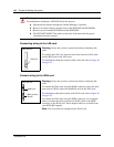
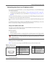
Connect wiring to the modem card
(North American Systems only)
Table 27 DB25 adapter cable
DB26 on
WAN card
Signal DB25 cable
DB26 on
WAN card
Signal DB25 cable
1 Chassis Ground 1 14 14
2 Transmit Data 2 15 Transmit Clock 15
3 Receive Data 3 16 16
4 Request to Send 4 17 Receive Clock 17
5 Clear to Send 5 18 18
6 Data Set Ready 6 19 19
7 Signal Ground/
Common Return
7 20 Data Terminal Ready 20
8 Data Carrier Detect 8 21 21
9 9 22 22
10 10 23 23
11 11 24 External Clock 24
12 12 25 25
13 13 26
Warning: Ensure the system is powered up before connecting this
cable.
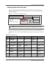
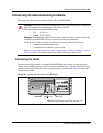
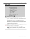
To connect the modem card, insert a PSTN line into the Line jack on
the modem card.
For information about the location of the modem card, refer to Figure
48 on page 143.
Note: Not all systems are equipped with a modem card.
RJ45 jack
Modem card face