


236 Chapter 17 Replacing the hard disk
P0993298 02
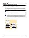
Routing power for mirrored systems
There are specific power cable configurations for the mirrored disks, depending on what system
you are using.
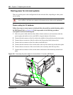
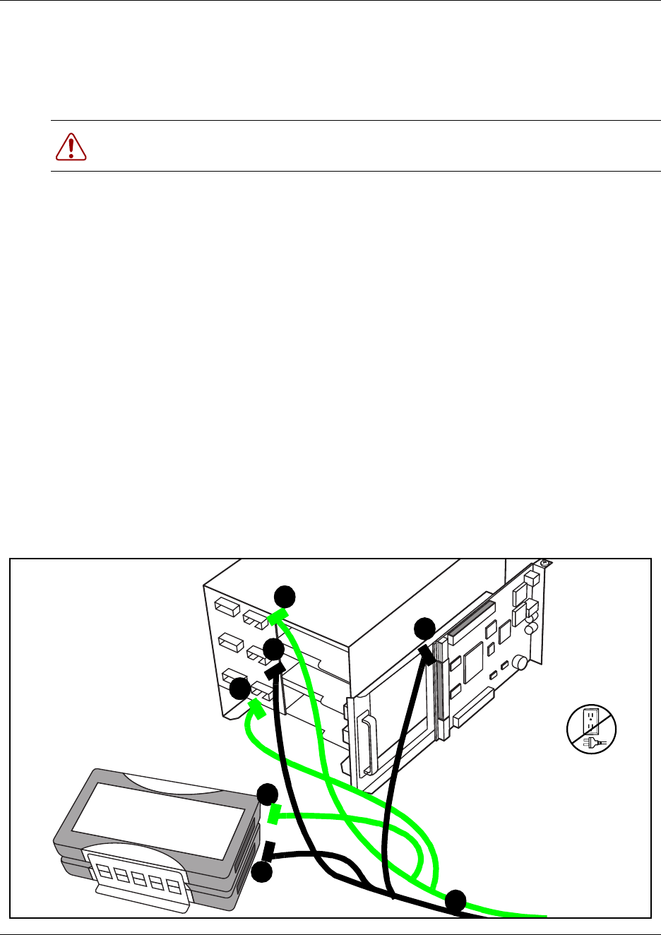
Power routing for 2.5 hardware
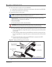
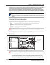
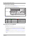
Follow these steps to connect power to the hard disks, the media bay module housing, and to
the RAID board. Refer to Figure 106. Each step number in the following procedure
corresponds to an item in the diagram.
1 Select two power cables that have three Molex female connectors and route them under the
power supply and media services card (MSC), along the bottom of the chassis.
2 Connect the end connector of the first cable to the middle of the media bay module back plane.
3 Connect the next connector of the first cable to the Primary hard disk (bottom disk).
4 Connect the last connector of the first cable to the RAID card.
5 Connect the end connector of the second cable to the top of the media bay module back plane.
6 Connect the next connector of the second cable to the secondary hard disk (top disk).
7 Connect the last connector of the second cable to the bottom of the media bay module back
plane.
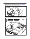
Figure 106 Connecting the power cables for mirrored disks, 2.5 version of BCM1000
Warning: Ensure that the cables on the front of the unit have been removed, and that
the ac power is off when you connect or disconnect power cables to this equipment.
2
3
4
5
6
7
1