


212 Chapter 15 Troubleshooting
P0993298 02
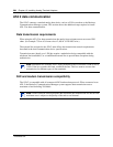
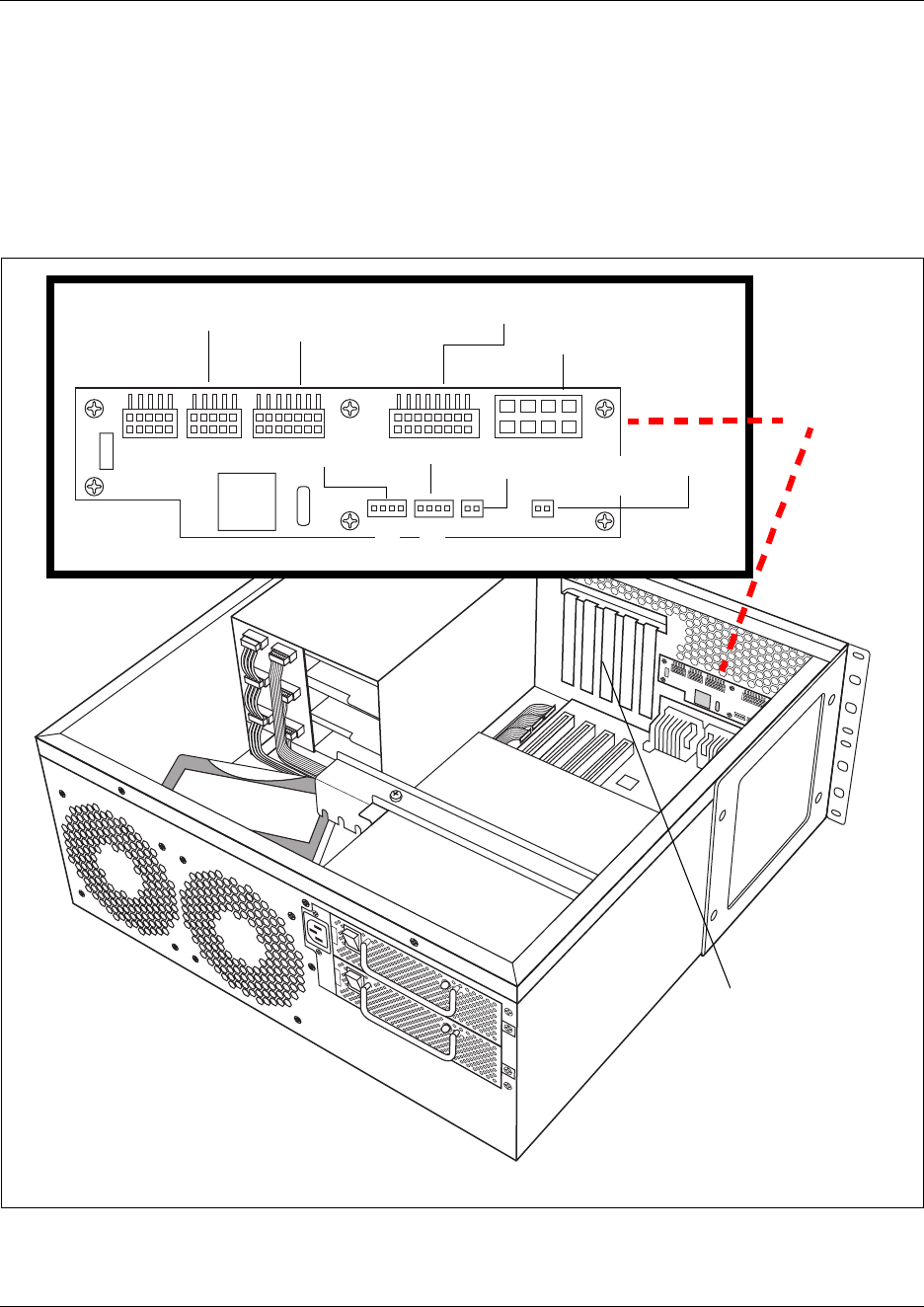
Using the System Status Monitor to monitor LEDs
The LEDs on the BCM1000 are part of the System Status Monitor (SSM) board.
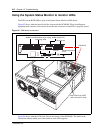
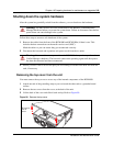
Figure 85 shows what the board looks like from inside the BCM1000. When installing new
equipment that connects to this board, ensure that the connector for that LED is properly seated.
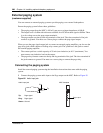
Figure 85 SSM board connections
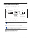
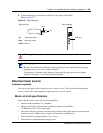
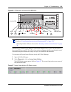
Figure 86 shows what the LEDs look like on the outside of the BCM1000. The labels in the
illustration indicate which part of the hardware each LED supports.
SSM board
J7
J6
Mother board
Redundant power supply
monitoring cable
Mother board (J10)
Board power
Redundant/primary fans
CPU fan
Remote temperature
sensor
Note: Chassis has all PCI
cards removed, for clarity