


BCM1000 version 3.0 addendum 17
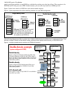
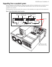
Setting module DIP switches for double density
Doubling the available telephone lines also requires additional DN records to accommodate the additional
telephones. The following charts show the DIP switch settings for single and double-density. Note that the ASM8s
do not have special double-density/single-density settings, whereas DSM16 and DSM32 modules must be set to
one mode or the other.
Note that the second set of 16 lines are not consecutively numbered from the first set. This was done to
accommodate existing installations.
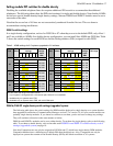
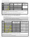
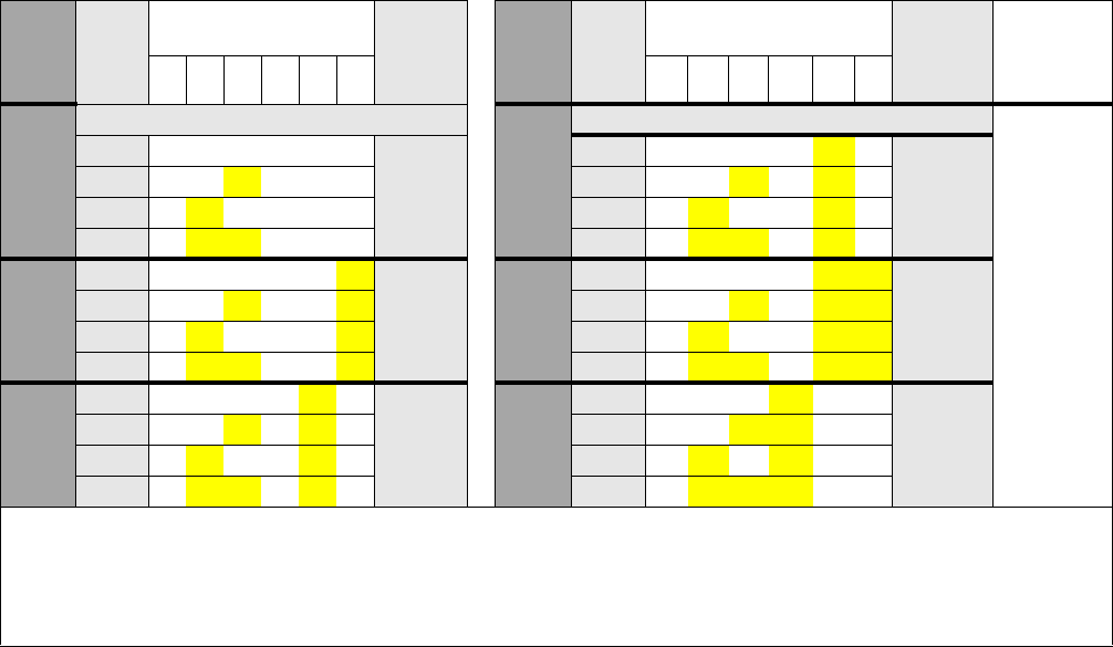
ASM 8 switch settings
In a single density configuration, such as for DS30 06 or 07 when they are set to the default PDD, only offset 1
and 2 are available to ASM8s. In a double-density configuration, you can install four ASM8s per DS30 bus. Table
2 shows the switch settings for each DS30 bus and the dialing numbers (DNs) assigned to each DS30.
DSM16/DSM 32 single density switch settings (upgraded system)
The following table shows the switch settings for DSM modules deployed as single density on a system that has
been upgraded from Business Communications Manager version 2.5 to version 3.0. All your current modules are
probably single-density modules. If you intend to continue to use them, you do not have to change any settings.
They will continue to function in the same manner as before.
DSM16+ and DSM32+ modules can be set to either density. To set them for single density, refer to the following
table. To set them to double density, refer to the table under
DSM16+ and DSM 32+ double density switch
settings (upgraded system) on page 18.
Note that Companion sets can only be assigned on DS30 06 and 07, which have single-density DSM modules.
Companion handsets have a different set of default DNs than the digital sets. Also, Companion can only be
deployed on systems that remain at Part Double Density (PDD), the default condition of 3.0 systems.
Table 2 ASM8 settings for 2.5 systems upgraded to 3.0 software
Select
bus
Select
offset
Enter these switch
settings
To
assign
these
DNs
Select
bus
Select
offset
Enter these switch
settings
To
assign
these
DNs
**Custom
DN range
123456 1 23 4 56
2.5 system upgraded to 3.0 2.5 system upgraded to 3.0
02
0 on on on on on on 221-228
05
0 on on on on off on 253-260
1 on on off on on on 228-236 1 on on off on off on 261-268
2 on offonononon377-384 2 on off on on off on 409-416
3 on off off on on on 385-392 3 on off off on off on 417-424
03
0 on on on on on off 237-244
06
0 on on on on off off 269-276
1 on on off on on off 245-252 1 on on off on off off 277-284
2 on off on on on off 393-400 ****2 on off on on off off 425-432
3 on off off on on off 401-408 ****3 on off off on off off 433-440
04
0 on on on on off on 253-260
07***
0 on on on off on on 285-292
1 on on off on off on 261-268 1 on on off off on on 293-300
2 on off on on off on 409-416 *****2 on off on off on on 441-448
3 on off off on off on 417-424 *****3 on off off off on on 449-456
** The extensions listed are based on a three-digit DN with a Start DN of 221. If your system has longer DNs or a different
Start DN, enter the range in the blank column.
*** If your system is configured with a 3/5 channel split, DS30 07 is not available.
****Available only on systems set to FDD.
*****Available only on systems set to FDD, with a 2/6 DS30 split.