198 Chapter 13 Installing Analog Terminal Adapters
P0993298 02
Analog transmission parameters
(North American systems only)
The following are the required analog parameters for an ATA2:
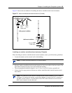
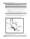
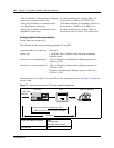
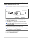
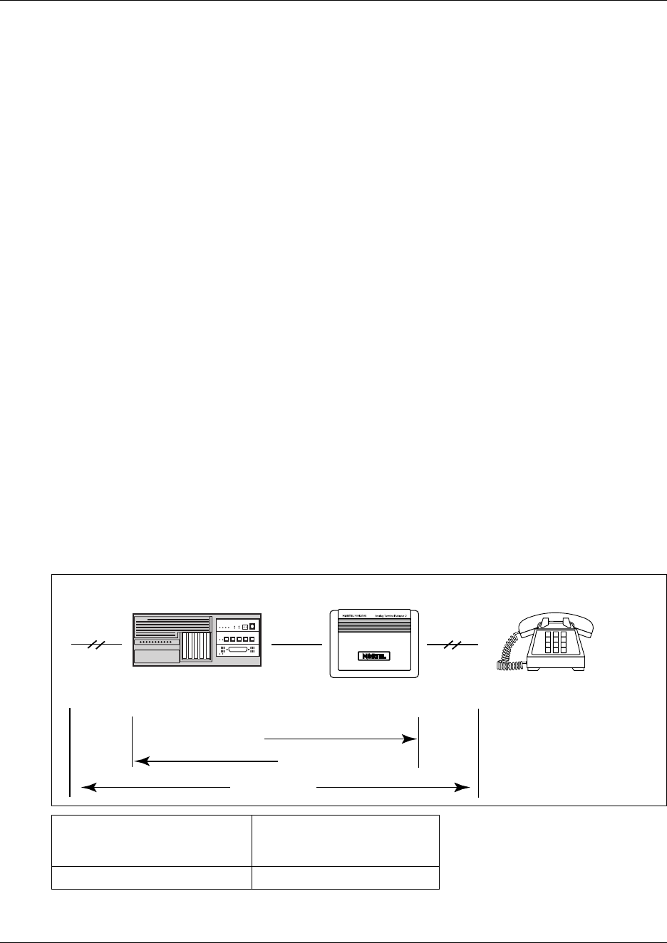
The maximum loss for ATA 2 to Central Office (CO) configuration, shown in Figure 75, must not
exceed 10 dB.
Figure 75 Insertion loss from the CO to the single-line telephone
ATA 2 to Business Communications Manager
system loop resistance (cable only)
135 ohms maximum (for example: 800 m of
0.5 mm wire or 2,600 ft. of 24 AWG wire)
Analog loop resistance on terminal side for
voice applications (cable only)
1,300 ohms maximum (for example: 4,600 m of
0.4 mm wire or 15,000 ft. of 26 AWG wire)
Analog loop resistance on terminal for data
applications (cable only)
200 ohms maximum (for example: 730 m of
0.4 mm wire side or 2,400 ft. of 26 AWG wire)
Input impedance at tip and ring 600 ohms
Return loss > 20 dB for 200 to 3,400 Hz (when Network terminated
with 600 ohms)
Insertion loss on an internal call ATA 2 to Business Communications Manager system loss
3.0 dB ± 0.5 dB
Insertion loss on an external call ATA 2 to Business Communications Manager system loss
2.2 dB ± 1.0 dB
Business Communications Manager system to ATA 2 loss
0.5 dB ± 1.0 dB
Longitudinal balance to ground 50 dB
60 to 4,000 Hz
With IEEE 455-1976 test
Overload level 3 dB
Single-line telephone
ATA 2
BCM1000
Business Communications Manager to ATA 2
ATA 2 to Business Communications Manager
10 dB Max
Cable loss
Central Office
cable loss


